Upgrading your car’s gauge cluster can significantly enhance your driving experience and provide crucial performance insights. For my project car, I decided to move away from the standard RCR-supplied Koso gauge cluster and integrate the Aim MXS Strada display. This display unit offers a compelling blend of features and value, positioning itself as a high-quality option for enthusiasts seeking comprehensive vehicle data without breaking the bank.
However, integrating aftermarket displays like the Aim MXS Strada, especially when tapping into your vehicle’s CAN system for engine data, can present unexpected challenges. One crucial point to consider is the potential conflict with your OBD2 diagnostic port. It’s essential to be aware that using an Aim dash or similar system to pull engine data from the CAN bus might impede access to the OBD2 port. This is because the dash can draw excessive current from the CAN system, effectively disabling the OBD2 diagnostic port. During my car tuning session, we encountered this exact issue and couldn’t get any readings from the OBD2 until the Aim dash was physically disconnected. To prevent this inconvenience, installing a toggle switch to easily cut power to the dash before tuning or diagnostic work is highly recommended. Alternatively, wiring the power to an easily accessible fuse in the fuse box allows for quick disconnection when needed. This valuable insight comes courtesy of Allan, highlighting a practical consideration for anyone integrating similar aftermarket systems.
Mounting the Aim MXS Strada Display
The Aim MXS Strada display is designed with rear-mounted bolts. This default mounting configuration can complicate installation and removal, especially when you prefer not to disassemble the entire dash. To address this, I devised a front-accessible mounting solution.
My approach involved creating a custom aluminum mounting plate for the Aim display. This plate would first receive the Aim MXS Strada, and then the plate assembly would be bolted to the dash from the front. This method allows for easy installation and removal of the display without requiring access to the back of the dash. Furthermore, I wanted to position the display approximately an inch closer to the steering wheel for optimal visibility. Instead of using spacers, I utilized reinforced resin to fill the gap and securely mount the aluminum plate.
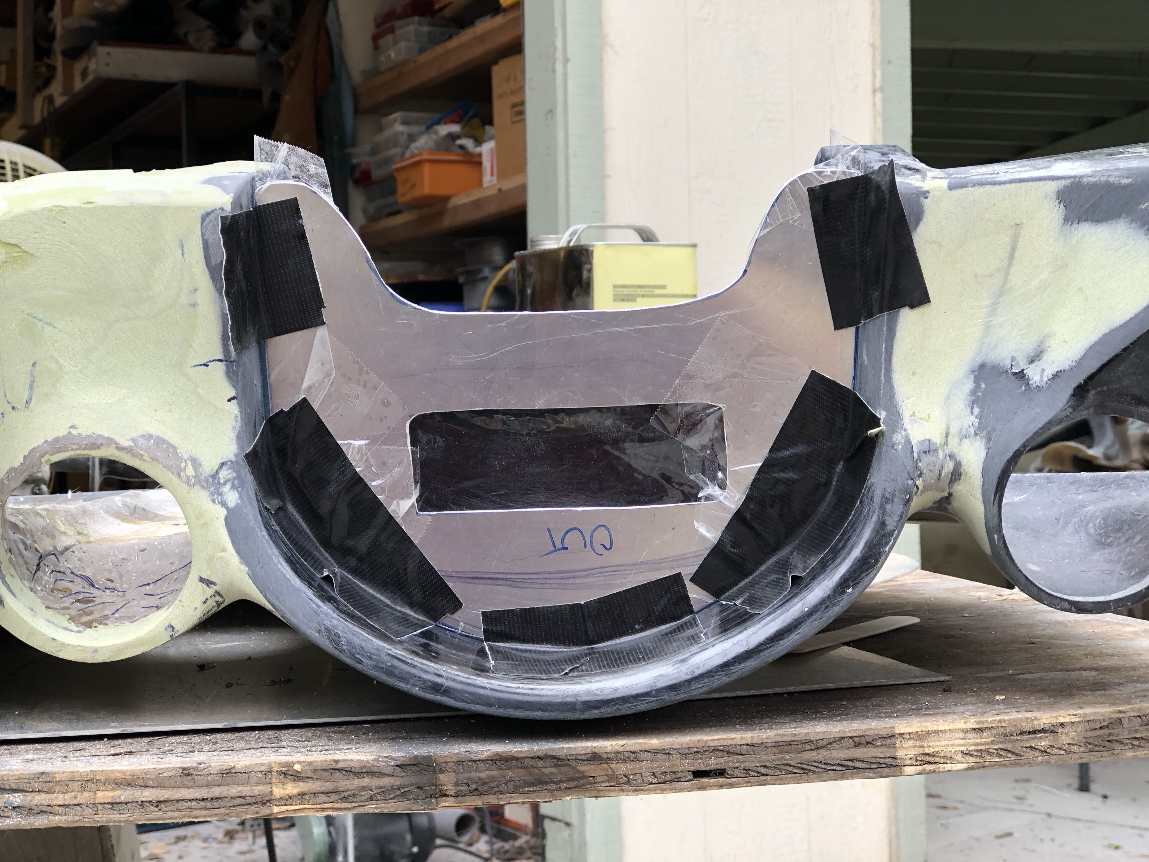
The image above shows the initial positioning of the aluminum panel on the dash, secured with tape to determine the desired placement before permanent mounting.
Here, you can see the aluminum panel spaced about an inch from the fiberglass dash, illustrating the gap that was filled with resin for reinforcement and to achieve the desired display position. The chopped glass strands mixed with resin are visible, emphasizing the reinforcement technique used for a robust mount.
This image showcases the aluminum panel after the resin has cured and the panel has been removed from the dash. The cured resin provides a solid base for mounting the Aim MXS Strada display, ensuring stability and proper spacing.
Blind holes were added to the aluminum panel to accommodate bolts that might be slightly longer than needed. This detail ensures a flush and secure fit for the mounting hardware, preventing any protrusion or interference.
Adhesive-mounted nuts were bonded to the aluminum panel using Plexus MA300 adhesive, known for its rapid curing time. This method provides strong and reliable threaded points for attaching the Aim MXS Strada display, simplifying the mounting process.
The mounting panel received a finishing touch to enhance its appearance, ensuring it integrates seamlessly with the vehicle’s interior aesthetics. This step focuses on the visual aspect of the installation, creating a clean and professional look.
The image above reveals the completed aluminum mounting panel, showcasing the final result after fabrication and finishing. It’s ready to receive the Aim MXS Strada display, demonstrating the custom mounting solution achieved.
Finally, the Aim MXS Strada display mounted onto the dash, illustrating the completed installation. The display is securely in place and positioned optimally within the driver’s view, ready for operation.
Aim MXS Strada Input Channels and OBD2 Data
The Aim MXS and MXG Strada displays are designed for vehicles that require essential sensor data display without extensive data logging capabilities. Out of the box, the Strada can handle up to four analog data channels, with expansion options available at an additional cost. For my setup, the four analog channels are dedicated to:
- Fuel Level: Utilizing a 0-90 Ohm converter from Iron Canyon Motorsports to interface with the fuel level sensor.
- Engine Oil Temperature: Requiring an additional temperature sensor from Aim for accurate readings.
- Headlight Status: Monitoring headlight activation (on/off).
- Turn Signal Status: Indicating turn signal activation (on/off).
Beyond these analog inputs, the Aim MXS Strada excels at leveraging data directly from the engine CPU via the vehicle’s OBD2 diagnostic port and its CAN signal wires. This integration provides access to critical engine parameters, including:
- Vehicle Speed: Acquired directly from the ECU’s data stream.
- Engine RPM: Real-time engine speed monitoring.
- Engine Coolant Temperature: Essential for engine health monitoring.
- Oil Pressure: Critical for lubrication system status.
- Intake Air Temperature: Important for performance and tuning insights.
- Battery Voltage: Monitoring the vehicle’s electrical system health.
It’s worth noting that factory GM crate engines typically have a limited number of sensors. The parameters listed above represent the fundamental data set needed to effectively monitor engine health and performance.
Regarding vehicle speed, initially, I opted for a Dakota Digital GPS sensor instead of relying on a traditional axle-mounted reluctor ring. This GPS sensor fed a signal to the ECU’s VSS input. However, discrepancies arose between the Dakota Digital’s indicated speed and the ECU’s reading. While theoretically, ECU coding adjustments could rectify this, verifying this with a tuner was necessary.
Post-build Update on Speed Sensing: I transitioned from the Dakota Digital speed sensor to the Aim GPS08 sensor. The Dakota Digital unit exhibited slow signal updates and eventually lost its output signal, possibly due to accidental reset during troubleshooting. Re-calibration was needed, and even then, the signal was not ideal. Instead of recalibrating the speedometer to compensate for the Dakota Digital’s signal, investing in the Aim GPS sensor proved to be a more robust solution. The Aim GPS08 offered quicker and more consistent speed updates, eliminating the “glitchy” feel at higher speeds. Although the Aim GPS sensor incurred an additional cost, the improved performance and reliability justified the switch, rendering the Dakota Digital unit largely redundant in this application. Tuning the car with the Aim GPS08 resulted in improved off-throttle behavior, suggesting that the Dakota Digital’s VSS signal was not contributing positively to engine idling or off-throttle performance.
Fuel Level Sensor Calibration
To accurately display the fuel level, the Iron Canyon Motorsports converter plays a crucial role. It transforms the RCR-supplied sensor’s output into a 0-5V signal compatible with the Aim MXS Strada. For the Strada version, the converter with Flying Leads is appropriate, while the full MXS system (non-Strada) requires the converter with 719 Binder leads. Installation is straightforward, following the provided instructions. Connect the wires to an analog input on the Aim display (I used analog input 1) and terminate them into the AMP connector.
The more intricate aspect is configuring the display to recognize and interpret this input correctly. The RaceStudio software, while powerful, is not inherently intuitive. The essential steps involve:
- Creating a Sensor: Define a sensor within RaceStudio, such as “Fuel Level,” and assign it to the chosen analog input (e.g., Analog 1).
- Sensor Calibration: Initiate the calibration process for the newly created sensor.
- Calibration Table Creation: Develop a calibration table specific to your fuel level sensor.
- Display Field Assignment: Assign the calibrated sensor to a designated field on the Aim MXS Strada display layout.
- Settings Transfer: Upload the updated configuration to the Aim MXS Strada unit.
For calibrating the fuel level sensor, I meticulously monitored the ICM converter’s output signal while adding fuel in one-gallon increments. Notably, no signal change was detected below approximately 1.9 gallons, indicating that readings below this level might be inaccurate. At around 17.75 gallons, fuel overflowed from the fuel vent port. With the fuel vent line connected, the tank’s capacity increases, potentially reaching around 20 gallons including the surge tank volume. To avoid overfilling, targeting a fill volume of approximately 17 gallons is recommended instead of filling until the fuel filler nozzle’s auto shut-off engages. Due to variations between vehicle builds and sensors, creating a custom calibration table is essential rather than relying on pre-existing tables. It’s crucial to use gasoline during calibration because the sensor relies on electrical resistance to measure fuel level, and gasoline and water have different resistance properties.
Post-build Fuel Capacity Update: With the fuel fill line properly connected, the system now accommodates approximately 2 additional gallons of fuel. This brings the total fuel capacity of the SLC to around 20 gallons, encompassing the surge tank volume.
Engine Oil Temperature and Other Sensor Inputs
Monitoring engine oil temperature involves a simpler setup. An additional 1/8″ NPT thermocouple, along with a patch cable, was installed into the threaded port on the engine oil cooler adapter. In RaceStudio software, designate an analog channel (analog channel 3 in my configuration) as an Aim-specific thermocouple, assign a descriptive name, and map it to a display field.
Integrating headlight and turn signal indicators is straightforward. Voltage signals from the steering column’s lighting stalk are fed into the Aim display. When the display detects voltage exceeding a predefined threshold, the corresponding indicator light is activated.
The Aim MXS Strada is available in “normal” and “street icon” versions. The “normal” version features three programmable lights on each side of the display, configurable for various alerts. The “street icon” version replaces these generic lights with icon-labeled indicators (headlight, high beam, fuel pump, oil symbol, etc.). The street icon version offers quicker visual interpretation of warnings, as a red flashing light next to the oil symbol immediately signals a potential oil pressure issue. However, the street icon version’s fixed icons can limit flexibility if all icons aren’t utilized or if different warnings are desired. Expanding analog channel inputs on the street icon version might require an expansion hub, adding to the cost. For instance, adding a high beam indicator might necessitate sacrificing one of the existing four analog channels or purchasing an expansion module, which may not be justifiable for every user. This could lead to unused, symbol-labeled warning lights on the display.
Recent updates to the Aim website suggest a refined street icon version where the warning light itself embodies the symbol, potentially offering a cleaner and more polished display compared to the earlier version with separate lights and icons.
Output Channel for Performance Optimization
A notable feature of the MXS Strada is its output channel. This channel can send a ground signal based on predefined conditions or alarms. A practical application is controlling the AC compressor based on engine RPM. The Sanden compressor in the Vintage Air system has a recommended maximum operating speed lower than the engine’s redline RPM. Exceeding this speed can damage the compressor. Therefore, it’s advisable to disengage the AC compressor before the engine reaches its maximum RPM.
By programming the Aim display to monitor engine RPM, the output channel can be configured to send a ground signal to a relay. This relay then interrupts the signal to the trinary switch, effectively turning off the AC compressor when the engine RPM approaches a predetermined limit. Determining the precise engine RPM threshold requires calculating the pulley ratios between the crankshaft and compressor and referencing the Sanden SD7B10 compressor’s maximum recommended operating speed (6000 RPM) and maximum speed (7000 RPM).
Aim RaceStudio Software and Programming
Programming the Aim MXS Strada using RaceStudio software is acknowledged as a less intuitive process. Expect a learning curve and dedicate sufficient time to familiarize yourself with the software’s functionalities. Fortunately, helpful video tutorials are available at https://vimeo.com/aimsports, courtesy of builder JTyrsing, which can significantly aid in navigating the software.
Steering Column Lighting Stalk Insights
The steering column included in the kit originates from an Oldsmobile Intrigue. Pinout information for this column is available in this post, thanks to KRoberts. Troubleshooting this column revealed that its outputs don’t adhere to typical +12V signal conventions. Key findings include:
- Low Beam and High Beam Lights: Output a ground signal, not +12V.
- Indicator (Parking Lights): Outputs a +12V signal only when the stalk is in the parking light position. In the low beam position, it behaves like a diode, exhibiting neither ground nor +12V signal.
- Turn Signals (Left and Right): Also behave like diodes, not providing a direct ground or +12V signal. Verification requires applying a load to the wire and visually confirming blinking lights (or a steady light for parking lights).
The unusual behavior of the turn signals might be related to using LED-specific flasher relays. JTyrsing’s testing on the same stalk indicated +12V outputs for indicator and turn signal circuits, suggesting potential variations based on relay types or wiring configurations. Understanding these nuances is crucial for correctly wiring and troubleshooting the Oldsmobile Intrigue steering column in custom vehicle builds. Allan’s suggestion that the stalk might be ground-signal based proved invaluable in resolving the troubleshooting challenges.