Have you ever found yourself staring at a jumble of wires under your car’s hood, wondering how they all connect to the OBD II connector? You’re not alone. Understanding the Obd Ii Connector Wiring Diagram is crucial for anyone who wants to diagnose car problems, access real-time data, or even just modify their car’s performance.
Understanding the Obd Ii Connector Wiring Diagram: Unveiling the Secrets of Your Car’s Electronics
The OBD II connector, often called the “diagnostic port,” is a standard interface that allows mechanics and car enthusiasts to access and communicate with your car’s onboard computer system. This system, known as the “Engine Control Unit” (ECU), monitors and controls various functions, including fuel injection, ignition timing, emissions, and more.
Imagine your car’s ECU as the brain of your vehicle, constantly receiving and processing data from various sensors throughout the car. The OBD II connector is like a bridge between your car’s brain and the outside world, allowing you to access that data and even influence it in some cases.
The OBD II Connector: A Gateway to Car Diagnostics and Beyond
The OBD II connector typically has 16 pins, each with a specific function. The OBD II connector wiring diagram details the function of each pin, including its signal type, voltage, and ground reference. This information is vital for understanding how the ECU communicates with different sensors and actuators within your car.
Here’s what makes the OBD II connector wiring diagram so important:
- Troubleshooting and Diagnostics: Mechanics use this diagram to pinpoint faulty sensors, diagnose engine problems, and understand the root cause of a Check Engine Light.
- Performance Tuning: Enthusiasts use the diagram to access and manipulate data related to engine parameters, enabling them to fine-tune their car’s performance.
- Data Logging: The OBD II connector can be used to log various data points from your car’s ECU, providing insights into your driving habits and vehicle’s health.
The Importance of the Obd Ii Connector Wiring Diagram: A Tale of Two Drivers
Imagine this scenario:
You’re driving down the road when your car starts sputtering. The Check Engine Light flashes on, and you pull over, worried. Armed with your OBD II connector wiring diagram and a code reader, you quickly diagnose the problem as a faulty oxygen sensor. With this knowledge, you can replace the sensor and be back on the road in no time.
Now consider this:
You’re driving a vintage European car, and you’re looking to improve its fuel efficiency. Using an OBD II connector wiring diagram, you identify the appropriate pins for accessing and adjusting fuel injection parameters. You connect a tuning device, adjust the settings, and instantly notice a significant improvement in fuel economy.
These are just two examples of how understanding the OBD II connector wiring diagram can empower you as a car owner.
Decoding the Obd Ii Connector Wiring Diagram: A Step-by-Step Guide
The OBD II connector wiring diagram is usually organized into two sections: Pinout and Signal Descriptions.
Pinout: This section shows the physical location of each pin on the connector, along with its assigned number.
Signal Descriptions: This section provides detailed information about each pin’s function, including:
- Signal Name: The specific name of the signal transmitted through that pin (e.g., “Engine Speed,” “Fuel Pressure”).
- Signal Type: Whether the signal is analog, digital, or a combination of both.
- Voltage: The voltage range that the signal operates within.
- Ground Reference: The pin number that serves as the ground reference for that specific signal.
Some common pins and their functions:
- Pin 1: Ground
- Pin 4: Battery Voltage
- Pin 5: Ground
- Pin 6: Engine Speed (RPM)
- Pin 16: CAN-High (Controller Area Network – High Speed Communication)
Where to Find the Obd Ii Connector Wiring Diagram: Navigating the Information Labyrinth
Obtaining the correct OBD II connector wiring diagram for your specific vehicle is crucial. Here are some resources:
- Vehicle Owner’s Manual: Many car manufacturers include a wiring diagram in the owner’s manual.
- Online Resources: Websites like AllDatadiy.com offer extensive technical information, including wiring diagrams, for a wide range of vehicles.
- Automotive Repair Manuals: Repair manuals specific to your car model will often include detailed wiring diagrams.
Beyond the OBD II Connector: A Deeper Dive into the Automotive Electrical System
The OBD II connector wiring diagram is just one piece of the puzzle when it comes to understanding your car’s electrical system. Other important components include:
- The ECU (Engine Control Unit): The brain of your car’s electrical system, responsible for controlling various functions and receiving data from sensors.
- Sensors: Devices that measure specific parameters within the engine and other systems (e.g., temperature, pressure, speed).
- Actuators: Devices that respond to signals from the ECU to control various aspects of the engine and other systems (e.g., fuel injectors, spark plugs).
- Wiring Harnesses: Bundles of wires that connect the various components of your car’s electrical system.
Frequently Asked Questions: Unraveling the Mysteries of the Obd Ii Connector Wiring Diagram
Q: Why is it so important to know the Obd Ii Connector Wiring Diagram?
Knowing the OBD II connector wiring diagram allows you to understand how the ECU communicates with various sensors and actuators within your car, which is crucial for troubleshooting, diagnostics, and performance tuning.
Q: Can I use a universal Obd Ii Connector Wiring Diagram?
While there is a standard OBD II connector with 16 pins, the specific signal assignments can vary depending on the car manufacturer and model year. You need a wiring diagram specific to your vehicle for accurate interpretation.
Q: What are some common Obd Ii Connector Wiring Diagram errors?
Common errors include incorrect pin assignments, incorrect signal descriptions, or missing information. Always double-check your source to ensure accuracy.
Q: How can I use the Obd Ii Connector Wiring Diagram for performance tuning?
By understanding the signal assignments for parameters like fuel injection timing, air-fuel ratios, and ignition timing, you can use tuning devices to adjust these values and improve your car’s performance.
Q: Are there any safety precautions I should take when working with the Obd Ii Connector Wiring Diagram?
Always disconnect the negative battery terminal before working on any electrical components, including the OBD II connector. Wear appropriate safety glasses and gloves to protect yourself from potential hazards.
Exploring the World of OBD II Diagnostics: Unlocking Your Car’s Secrets
The OBD II connector wiring diagram is an essential tool for anyone who wants to understand their car’s electrical system, troubleshoot problems, and potentially enhance its performance.
By taking the time to understand the diagram’s intricacies, you can gain valuable insights into how your car operates and unlock its full potential.
Remember, this is just the tip of the iceberg when it comes to the world of automotive electronics! For more in-depth information on specific car models or advanced diagnostic techniques, explore the wealth of resources available online and consult with trusted professionals.
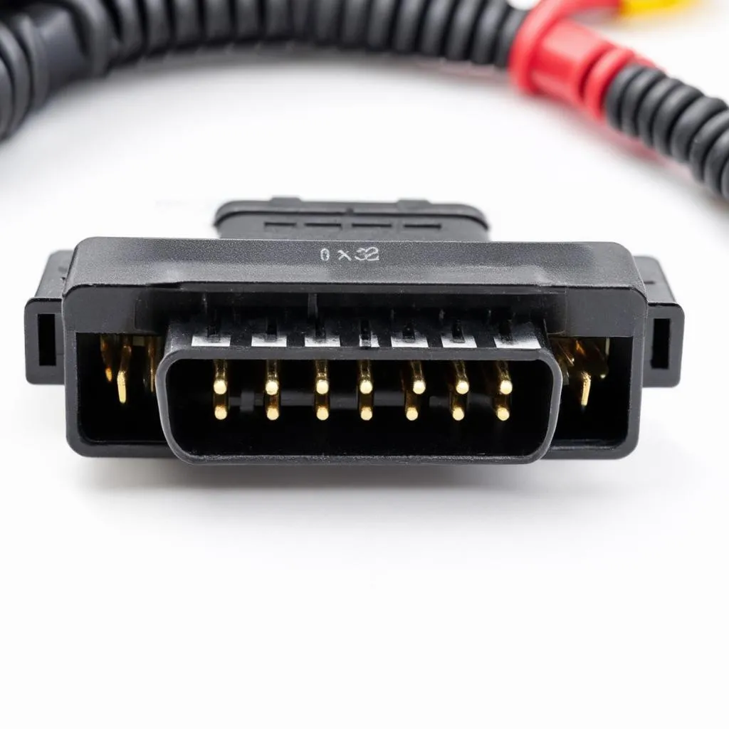 OBD II Connector Wiring Diagram
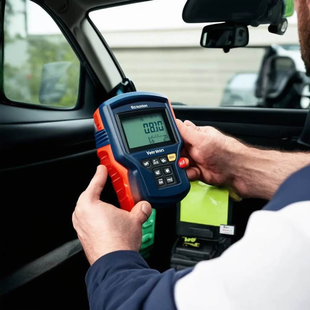 OBD II Scanner
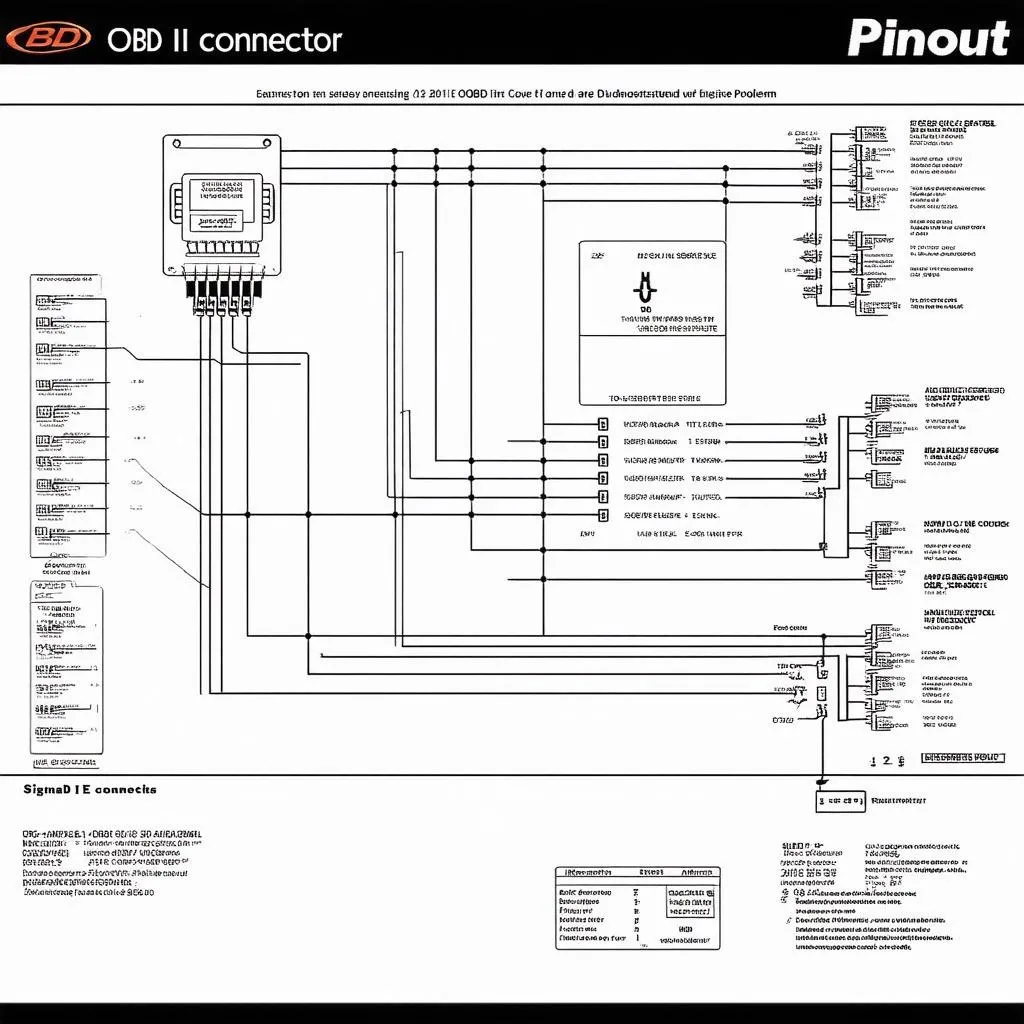 OBD II Connector Wiring Diagram Close-Up
Don’t hesitate to reach out to us for any questions or concerns about your car’s electrical system. Our team of automotive experts is available 24/7 to provide support and guidance.
Whatsapp: +84767531508
Happy driving!