Are you a Yamaha motorcycle owner looking to understand and troubleshoot your bike’s diagnostics without relying on expensive dealership services? Creating your own Yamaha diagnostic adapter is a cost-effective solution. This guide will walk you through building a 4-pin Yamaha diagnostic connector to OBD2 adapter, allowing you to interface with standard OBD2 scanners.
Disclaimer: This guide is for informational purposes only. I am not a professional mechanic, and this is based on my personal experience. Follow these steps at your own risk. I am not responsible for any damage to your motorcycle, diagnostic equipment, or any unforeseen issues that may arise from using this guide.
Tools and Parts You’ll Need
Before starting, gather these essential tools and parts:
Tools:
- Wire strippers/cutters
- Needle-nose pliers
- Soldering iron (Recommended for a robust connection)
- Molex crimping tool (Optional, but simplifies pin crimping)
Parts:
- 4-Pin Connector: Specifically designed for Yamaha diagnostics (Corsa Technic – 4-Pin Connector). Ensure it’s compatible with 22-16AWG wire and 1.3-1.7mm insulation.
- OBD-II Cable: An OBD2 extension cable with a female connector (Corsa Technic – OBD-II Cable). This provides the OBD2 interface.
For budget-conscious builders, you can source a female OBD-II connector separately and use spare wires you may have. However, ensure you select the correct 4-pin connector to match your wire gauge.
Understanding the Wiring: OBD2 Connector Pinout for Yamaha Diagnostics
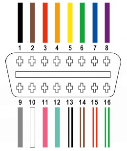
Out of the 16 pins on a standard OBD-II connector (OBD2C), we will only be utilizing four crucial wires for Yamaha motorcycle diagnostics. These connections are vital for CAN bus communication and power supply:
- Pin 4 (Chassis Ground): Typically an orange wire on the OBD2C. Provides the ground reference.
- Pin 6 (CAN [J-2234] High): Usually a green wire on the OBD2C. Carries the CAN High signal.
- Pin 14 (CAN [J-2234] Low): Commonly a brown wire with a white stripe on the OBD2C. Carries the CAN Low signal.
- Pin 16 (Battery Power): Often a green wire with a white stripe on the OBD2C. Supplies power to the diagnostic tool.
Step-by-Step Guide to Building Your Yamaha Diagnostic Adapter
Let’s proceed with the construction of your Yamaha 4-pin to OBD2 adapter. Follow these steps carefully:
Step 1: Preparing the OBD-II Cable Wires
The OBD-II cable wires are often thin (26AWG), which is smaller than the pins on the 4-pin connector (designed for 22AWG). To ensure a secure connection, we need to prepare the wires.
- Expose the Wires: Carefully remove the outer sheath and shielding from the OBD-II cable to access the individual wires.
- Separate the Required Wires: Isolate the four wires corresponding to pins 4, 6, 14, and 16 as listed in the pinout section.
- Manage Unused Wires: Bundle the remaining 12 unused wires and secure them with a zip tie to keep them out of the way and prevent accidental shorts.
Step 2: Preparing the Wire Ends for the 4-Pin Connector
Due to the thin gauge of the OBD-II cable wires, we need to thicken them to fit securely into the 4-pin connector pins.
- Strip Wire Insulation: Strip approximately 3/8 inch of insulation from the end of each of the four wires.
- Thicken the Wire: Fold the exposed wire strands over onto themselves and twist them tightly. This effectively doubles the wire thickness, making it a better fit for the connector pins.
- Slide Rubber Seals: The 4-pin connector kit includes rubber seals. Slide one seal onto each of the prepared wires. These seals provide environmental protection at the connector.
Step 3: Attaching Pins to the Wires
The 4-pin connector uses crimp pins to establish electrical contact. Each pin has two sets of prongs: one for the wire strands and one for the insulation seal.
- Insert Wire into Pin: Insert the thickened wire into the pin, ensuring the wire strands align with the front set of prongs (closest to the pin tip).
- Secure Wire for Crimping/Soldering: Use needle-nose pliers to hold the wire in place within the pin. This is especially helpful if you plan to solder, or if you don’t have a crimping tool.
Step 4: Soldering (Recommended) or Crimping the Wire to the Pin
For a reliable and robust connection, soldering is highly recommended, especially given the small wire gauge. If you prefer crimping and have the correct tool, that’s also an option.
Soldering:
- Solder the Wire: Apply solder to the wire strands within the pin. Ensure the solder flows smoothly, creating a solid electrical and mechanical connection.
- Allow to Cool: Let the solder joint cool completely before proceeding to the next step.
Crimping (Alternative):
- Crimp Wire Prongs: If you have a Molex crimping tool, use it to crimp the front set of prongs (wire prongs) securely around the wire strands.
- Manual Crimping (Without Tool): If you don’t have a crimping tool, use needle-nose pliers to carefully fold over the wire prongs, ensuring they tightly grip the wire. Refer to online video tutorials for crimping techniques using pliers (Crimping with Pliers – YouTube).
Step 6: Crimping the Insulation Seal Prongs
After securing the wire strands, crimp the second set of prongs (insulation prongs) over the rubber seal to provide strain relief and environmental protection.
- Slide Seal into Position: Slide the rubber seal up the wire until it sits between the insulation prongs of the pin.
- Crimp Seal Prongs: Use a crimping tool or needle-nose pliers to fold the insulation prongs over the rubber seal, securing it in place.
Step 7: Wire Pairing (Recommended)
Although the reason isn’t definitively known, many DIY guides recommend twisting pairs of wires. This may help reduce electromagnetic interference.
- Pair the Wires: Twist the following wire pairs together:
- Pin 4 (orange) / Pin 16 (green w/white stripe) – Power and Ground
- Pin 6 (green) / Pin 14 (brown w/white stripe) – CAN High and CAN Low
Step 8: Inserting Pins into the 4-Pin Connector Housing
Finally, insert the completed pins into the 4-pin connector housing in the correct orientation.
-
Pinout Orientation: Refer to the diagram below and insert the pins into the corresponding slots in the 4-pin connector housing:
- Slot A: Pin 14 (brown w/white stripe) – CAN Low
- Slot B: Pin 6 (green) – CAN High
- Slot C: Pin 16 (green w/white stripe) – Battery Power
- Slot D: Pin 4 (orange) – Chassis Ground
-
Insert and Lock Pins: Push each pin into the rear of the connector housing until you hear a click. This indicates the pin is locked in place. You can use needle-nose pliers to gently pull on the wire to ensure the pin is securely locked.
Your Yamaha Diagnostic Adapter is Complete!
Congratulations! You have successfully built your own Yamaha 4-pin to OBD2 diagnostic adapter.
Testing Your Adapter
Before relying on your adapter, test it to ensure it functions correctly. Connect it to your Yamaha motorcycle and an OBD2 scanner.
You should now be able to read diagnostic codes, clear errors, and access other diagnostic information from your Yamaha motorcycle using a standard OBD2 scanner.
If any step is unclear, or if you encounter issues, review the instructions and images again. Feel free to ask for clarification if needed!