Disclaimer: I am not a professional mechanic, just a DIY enthusiast who has successfully completed this process. This guide is based on my personal experience, and while I hope it works for you, I am not responsible for any issues that may arise. Proceed at your own risk. This includes, but is not limited to, damage to your vehicle’s ECU, malfunctioning harnesses, or unintended interdimensional consequences.
Building your own OBD2 connector harness can be a rewarding project for any car enthusiast or DIYer. Whether you are creating a custom diagnostic setup, modifying your vehicle for specific data logging, or simply replacing a damaged connector, understanding where to source the right components is crucial. This guide will walk you through the process of creating a simple OBD2 harness, focusing on Where To Buy Obd2 Connector Female Pins and other necessary parts.
To get started, you’ll need a few basic tools and components. Here’s what I used:
Tools:
- Wire strippers/cutters
- Needle-nose pliers
- Molex crimping tool (optional, but highly recommended for professional results)
- Soldering iron and solder (recommended for enhanced connection reliability, but crimping can suffice)
Parts:
- 4-Pin Connector (Corsa Technic 4-Pin Connector; suitable for 22-16AWG wire; insulation/seal size = 1.3-1.7mm)
- OBD-II Cable (Corsa Technic OBD-II Cable)
For those looking to minimize costs and already have spare automotive wire, you can purchase the female OBD-II connector and individual OBD2 connector female pins separately. This approach requires you to determine your wire gauge to ensure compatibility with the connector pins. Knowing the correct wire size is essential when you are looking for where to buy OBD2 connector female pins to guarantee a secure and reliable connection.
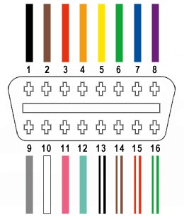
From the 16 available pins on a standard OBD-II connector (OBD2C), we will only be utilizing four for this simplified harness:
- Pin 4: Chassis Ground (typically an orange wire on the OBD2C cable)
- Pin 6: CAN High (CAN J-2234 High, typically a green wire on the OBD2C cable)
- Pin 14: CAN Low (CAN J-2234 Low, typically a brown wire with a white stripe on the OBD2C cable)
- Pin 16: Battery Power (typically a green wire with a white stripe on the OBD2C cable)
A diagram illustrating the OBD2 connector pinout, highlighting pins 4, 6, 14, and 16 which are essential for basic OBD2 functionality and relevant to discussions about where to buy OBD2 connector female pins.
Step-by-Step Guide to Building Your OBD2 Harness
Step 1: Preparing the OBD-II Cable
Following recommendations from other guides, twisting wire pairs is beneficial for reducing electromagnetic interference. Therefore, our first step involves preparing the OBD-II cable. Begin by carefully removing the outer sheath and shielding from the OBD2C cable to access the internal wires. Identify and separate the four wires we’ll be using (pins 4, 6, 14, and 16) from the rest. To keep the unused wires organized and out of the way, bundle them together and secure them with a zip tie.
Image showing the OBD2 cable with its outer sheath and shielding removed, a visual step in preparing the cable for harness construction and relevant for DIYers searching where to buy OBD2 connector female pins for similar projects.
Image displaying the four selected wires (pins 4, 6, 14, 16) separated from the OBD2 cable, ready for connection, illustrating a key stage after sourcing OBD2 connector female pins and other components.
Step 2: Preparing the Wires and Seals
A slight incompatibility arose with the parts I used: the wires in the OBD2C are 26AWG, while the pins for the 4-pin connector (4PC) are designed for 22AWG wires. To compensate for this difference, we need to “thicken” the wire ends. The OBD2C wires come pre-stripped with a short exposed length (approximately 1/8 inch). Carefully strip off more insulation to expose about 3/8 inch of wire. Fold the exposed wire over itself and twist it tightly. This will increase the wire thickness to better fit the 22AWG rated pins.
The 4PC kit includes rubber seals, which are crucial for protecting the connection from environmental factors. Slide one rubber seal onto each of the four prepared wires.
A close-up image of the wires with insulation stripped and rubber seals slid onto them, demonstrating the preparation before attaching OBD2 connector female pins, a vital step for those learning where to buy OBD2 connector female pins and how to use them.
Step 3: Inserting Wires into Connector Pins
Now we’ll work with the OBD2 connector female pins for the 4-pin connector. These pins have two sets of prongs: one set to crimp onto the exposed wire and another to crimp onto the rubber seal. Insert the exposed, thickened wire into the front set of prongs on a pin. Ensure the wire is properly positioned within the prongs. Due to the small gauge of the wire relative to the pin size, using needle-nose pliers to hold the wire in place during the next step is highly recommended.
Image illustrating a wire inserted into an OBD2 connector female pin, highlighting the size disparity and need for careful handling when working with these small components after finding where to buy OBD2 connector female pins.
Step 4: Soldering (Recommended) or Crimping the Wires
At this stage, you have two options for securing the wire to the connector pin: soldering or crimping. Soldering provides a robust and electrically sound connection, which is particularly beneficial given the small wire size. If you choose to solder, apply solder to the area where the wire meets the pin, ensuring a solid bond. If you’re new to soldering, online resources like YouTube tutorials can be very helpful.
Soldering Tips and Tricks on YouTube
Image showing a wire soldered to an OBD2 connector female pin, demonstrating the soldered connection option for enhanced durability, particularly useful information for those who have sourced OBD2 connector female pins and are looking for reliable assembly methods.
Step 5: Crimping the Wire (Alternative to Soldering)
If you prefer crimping, or do not have soldering equipment, use a Molex crimping tool for the best results. This tool is designed to properly crimp these types of connectors. However, if you don’t have access to a specialized crimping tool, needle-nose pliers can be used as an alternative.
Using needle-nose pliers, carefully fold one prong at a time over the wire. Start at an angle and gradually crimp the prongs down, ensuring a secure mechanical connection. While perhaps overkill, you can further secure the connection by gently crushing the prongs a bit more with the pliers.
Image showing the process of crimping an OBD2 connector female pin onto a wire using pliers, illustrating an alternative assembly method for those who may not have soldering equipment or are exploring options after deciding where to buy OBD2 connector female pins.
Close-up image of a crimped OBD2 connector female pin, demonstrating the completed crimped connection as an alternative to soldering, providing visual guidance for users working with OBD2 connector female pins purchased for DIY projects.
Step 6: Crimping the Seal
Slide the rubber seal up the wire until it is positioned between the rear set of prongs on the connector pin. Using the same crimping technique as before (either with a crimping tool or needle-nose pliers), fold these prongs over the rubber seal. This secures the seal and provides strain relief and environmental protection for the connection.
Image showing the initial step of crimping the rubber seal onto the OBD2 connector female pin, demonstrating how to secure the seal for environmental protection and strain relief after attaching OBD2 connector female pins.
Image showing the process of folding prongs over the rubber seal on an OBD2 connector female pin, highlighting the technique used to secure the seal and enhance connection durability when using OBD2 connector female pins.
Image of a completed OBD2 connector female pin with the seal crimped, illustrating the final step in pin preparation and emphasizing the importance of environmental sealing for long-term reliability after sourcing OBD2 connector female pins.
Step 7: Wire Pairing (Recommended)
Although the exact reason isn’t definitively stated in all guides, it’s often recommended to twist specific wire pairs together in DIY OBD2 harnesses. This practice is likely to further minimize potential electromagnetic interference. Pair and twist the wires as follows:
- Pin 4 (orange) and Pin 16 (green with white stripe)
- Pin 6 (green) and Pin 14 (brown with white stripe)
Step 8: Inserting Pins into the 4-Pin Connector Housing
Finally, insert the completed pins into the 4-pin connector housing (4PC) in the correct orientation. Refer to the diagram below for proper pin placement:
- Pin 14 (brown w/white stripe) > Connector Slot A
- Pin 6 (green) > Connector Slot B
- Pin 16 (green w/white stripe) > Connector Slot C
- Pin 4 (orange) > Connector Slot D
Push each pin into the rear of the connector housing until you hear an audible “click,” indicating that the pin is locked securely in place. Using needle-nose pliers can assist in gently pulling the wire from the back to ensure the pin is fully seated and locked.
Diagram showing the 4-pin connector with pin assignments for slots A, B, C, and D, crucial for correctly inserting OBD2 connector female pins and completing the harness assembly, especially for users who have recently purchased OBD2 connector female pins.
Completion and Testing
Front view image of the completed OBD2 harness, showcasing the assembled connector and wiring, representing the final product after following steps on where to buy OBD2 connector female pins and how to assemble them.
Angled view of the finished OBD2 harness, providing a different perspective of the completed assembly and demonstrating the outcome of a DIY project focused on where to buy OBD2 connector female pins and harness construction.
Congratulations! Your DIY OBD2 harness is now complete.
I successfully tested this harness to diagnose and clear a self-induced error code in my vehicle.
Image of the OBD2 harness being used to clear an error code, demonstrating the functionality of the DIY harness and validating the process of sourcing and assembling OBD2 connector female pins and related components.
If any step in this guide is unclear, or if you require further clarification, please don’t hesitate to ask. I can provide additional photos or explanations to help you through the process.