Understanding your vehicle’s health is becoming increasingly important, and the OBD2 cable is a key tool in this process. If you’ve ever wondered about the “check engine” light or how mechanics diagnose car problems, the OBD2 cable is central to the answer. This guide will provide a comprehensive yet simple introduction to OBD2 cables, their function, and why they are essential for modern vehicle diagnostics.
Decoding OBD2: On-Board Diagnostics Explained
OBD2 stands for On-Board Diagnostics, second generation. It’s essentially your car’s built-in self-diagnostic system. Standardized across the automotive industry, OBD2 allows access to crucial data about your vehicle’s performance and health. This system monitors various components, most importantly emission controls, and reports any issues it detects. The OBD2 system communicates this information primarily through Diagnostic Trouble Codes (DTCs) and real-time data parameters.
You likely first encounter OBD2 when that dreaded Malfunction Indicator Light (MIL), often called the “check engine light,” illuminates on your dashboard. This light is a signal from your car’s computer indicating a problem has been detected. To understand what’s wrong, mechanics use an OBD2 scanner or diagnostic tool. This tool connects to your car via the OBD2 cable and retrieves the diagnostic information.
The process is straightforward: a mechanic plugs the OBD2 cable into the standardized 16-pin OBD2 connector, usually located under the dashboard near the steering wheel. The OBD2 scanner then sends requests through the cable, and the car responds with data. This data can include everything from engine speed and temperature to oxygen sensor readings and, crucially, those Diagnostic Trouble Codes. These codes pinpoint the source of the problem, allowing for faster and more accurate repairs.
Does Your Car Use an OBD2 Cable? Compatibility and History
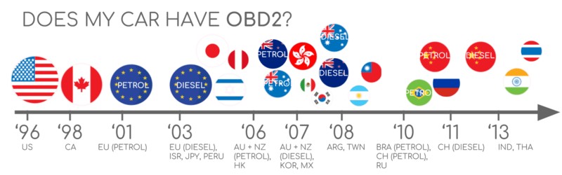
The question of OBD2 compatibility is usually a simple one for modern vehicles: almost certainly, yes.
Nearly all gasoline cars manufactured after 2001 in Europe and 1996 in the USA, as well as diesel cars after 2004 in Europe, are OBD2 compliant. In the US, OBD2 became mandatory for cars and light trucks in 1996, and regulations expanded to include medium and heavy-duty vehicles in later years. The adoption of OBD2 was driven by emissions control standards, spearheaded by the California Air Resources Board (CARB) starting in 1991. The Society of Automotive Engineers (SAE) played a crucial role in standardizing OBD2, ensuring uniformity across different manufacturers with standards like SAE J1962 for the OBD2 connector and standardized DTCs.
However, for older vehicles, particularly those pre-dating these mandates, compatibility can be less certain. Even if an older car has a 16-pin connector that looks like an OBD2 port, it might not actually support the OBD2 protocol. Compliance is generally linked to the vehicle’s market and year of manufacture.
A Brief History of OBD2 Development
- 1991: California Air Resources Board (CARB) mandates OBD for emission control in new cars.
- 1996: OBD2 becomes mandatory in the USA for cars and light trucks.
- 2001: OBD2 required in the EU for gasoline cars (EOBD).
- 2003: OBD2 required in the EU for diesel cars (EOBD).
- 2005: OBD2 required in the US for medium-duty vehicles.
- 2008: US cars mandated to use ISO 15765-4 (CAN) as the OBD2 communication basis.
- 2010: OBD2 required in US heavy-duty vehicles.
This phased rollout reflects the increasing importance of standardized vehicle diagnostics, primarily for emissions but also for broader vehicle health monitoring.
The Future of OBD and OBD2 Cables
While OBD2 is firmly established, the automotive world is evolving, and so is vehicle diagnostics. Several trends are shaping the future of OBD and, by extension, the role of the OBD2 cable.
OBD and Electric Vehicles
Interestingly, traditional OBD2 as originally legislated for emission control is not strictly required for electric vehicles (EVs). Consequently, many modern EVs do not fully support standard OBD2 requests. Instead, they often utilize manufacturer-specific protocols like UDS (Unified Diagnostic Services) for communication. This makes accessing diagnostic data from EVs more complex, often requiring reverse engineering to understand the communication protocols. However, as EVs become more mainstream, standardization in EV diagnostics is likely to evolve.
WWH-OBD and OBDonUDS: Modern OBD Evolutions
To address limitations in data richness and communication protocols of the original OBD2, newer standards like WWH-OBD (World Wide Harmonized OBD) and OBDonUDS (OBD on UDS) have emerged. These aim to modernize OBD communication by building upon the UDS protocol, offering more streamlined and enhanced diagnostic capabilities.
OBD3 and Telematics: The Connected Car
The concept of OBD3 envisions integrating telematics into vehicle diagnostics. This could involve embedding a radio transponder in vehicles to wirelessly transmit Vehicle Identification Numbers (VIN) and DTCs to a central server for remote monitoring and emissions testing. While this offers convenience and efficiency, it also raises privacy concerns related to data collection and surveillance. Many existing devices already facilitate wireless OBD2 data transfer, such as WiFi or cellular-enabled CAN loggers.
Potential Restrictions on Third-Party OBD2 Access
There’s ongoing debate about restricting third-party access to OBD2 data. Some automotive manufacturers argue that OBD2 was designed for repair shops, not for enabling a data-driven economy through third-party services. Proposals to limit OBD2 functionality while driving and centralize data collection with manufacturers have surfaced, citing security concerns and control over “automotive big data.” This could significantly impact the market for aftermarket OBD2-based services and tools.
OBD2 Standards and the OBD2 Cable Connector
OBD2 operates as a higher-layer protocol, much like a language used for communication. It often utilizes CAN (Controller Area Network) bus as its communication method, similar to how a phone uses a network for communication. OBD2 is comparable to other CAN-based protocols like J1939 (used in heavy-duty vehicles), CANopen (industrial control), and NMEA 2000 (marine electronics).
OBD2 standards comprehensively define various aspects, including the OBD2 connector, lower-layer communication protocols, and OBD2 Parameter IDs (PIDs), which are codes used to request specific data. These standards are often structured around the 7-layer OSI model for network communication. Organizations like SAE and ISO have contributed to these standards, with SAE standards often originating in the US and ISO standards having broader international application. Many SAE and ISO standards for OBD2 are technically very similar, such as SAE J1979 and ISO 15031-5 (for diagnostic services) and SAE J1962 and ISO 15031-3 (for the OBD2 connector).
The OBD2 Connector: SAE J1962 Standard
The physical interface for accessing OBD2 data is the OBD2 connector, standardized as SAE J1962 (and ISO 15031-3). This is the 16-pin connector you plug your OBD2 cable into.
The OBD2 connector is typically a 16-pin Data Link Connector (DLC) Type A. Key features include:
- Location: Usually located within reach of the driver, often under the dashboard. However, its exact location can sometimes be concealed behind a panel.
- Pin 16: Provides battery power, even when the ignition is off, allowing the OBD2 system to function continuously for certain monitoring tasks.
- Pinout: The specific function of each pin varies depending on the communication protocol used by the vehicle.
- CAN bus Pins: For vehicles using CAN bus (the most common modern protocol for OBD2), pins 6 (CAN High) and 14 (CAN Low) are the active communication lines.
OBD2 Connector Types: Type A vs. Type B
While Type A is standard in cars, you may encounter Type B OBD2 connectors, especially in medium and heavy-duty vehicles. Both types share a similar pin layout, but Type B is designed for 24V systems common in trucks, whereas Type A is for 12V systems in cars. Type B connectors also often use different communication baud rates (e.g., 250K vs. 500K in cars). Visually, Type B connectors have a distinguishing interrupted groove in the middle. Interestingly, a Type B OBD2 adapter cable is usually compatible with both Type A and Type B sockets, but a Type A adapter will not fit into a Type B socket.
OBD2 Communication and CAN bus: ISO 15765-4
Since 2008, CAN bus, as defined by ISO 15765-4 (also known as Diagnostics over CAN or DoCAN), has been mandatory for OBD2 communication in US vehicles. ISO 15765-4 standardizes the use of CAN for diagnostic communication, focusing on the physical, data link, and network layers. Key aspects standardized include:
- Bit-rate: CAN bus speed must be either 250 Kbps or 500 Kbps.
- CAN IDs: Both 11-bit (standard) and 29-bit (extended) CAN identifiers are permitted.
- Specific CAN IDs: Defined CAN IDs are reserved for OBD requests and responses.
- Data Length: Diagnostic CAN frames must have a data payload of 8 bytes.
- Cable Length: The OBD2 adapter cable is specified to have a maximum length of 5 meters.
OBD2 CAN Identifiers (11-bit and 29-bit)
OBD2 communication is based on a request-response model. In most cars, 11-bit CAN IDs are used for OBD2. Functional addressing, using CAN ID 0x7DF, is common, where a request is broadcast to all OBD2-compliant Electronic Control Units (ECUs). Physical addressing, using CAN IDs 0x7E0-0x7E7 to target specific ECUs, is less frequently used. ECU responses typically use 11-bit IDs in the range 0x7E8-0x7EF. The most common response ID is 0x7E8 from the Engine Control Module (ECM), with 0x7E9 from the Transmission Control Module (TCM) also being relatively common.
In some vehicles, especially larger ones like vans and trucks, 29-bit extended CAN identifiers may be used for OBD2. Here, the functional addressing CAN ID is 0x18DB33F1. Responses in 29-bit CAN typically fall in the range of 0x18DAF100 to 0x18DAF1FF, often 0x18DAF110 and 0x18DAF11E. These 29-bit IDs are also sometimes represented in J1939 PGN (Parameter Group Number) format, with the response ID often corresponding to PGN 0xDA00 (55808), which is reserved for ISO 15765-2 in the J1939-71 standard.
OBD2 vs. Proprietary CAN Protocols: Understanding the Difference
It’s crucial to understand that OBD2 is not the primary communication protocol for your car’s internal operations. Vehicle manufacturers (OEMs) use their own proprietary CAN protocols for ECU communication and control. These OEM-specific protocols are unique to vehicle brands, models, and years. Unless you have OEM documentation or engage in reverse engineering, this data is generally inaccessible and undecipherable.
When you connect an OBD2 cable and a CAN bus data logger to your car’s OBD2 port, you might observe both OBD2 communication and the OEM-specific CAN data traffic simultaneously. In many newer vehicles, a gateway module might filter or block access to the OEM-specific CAN data through the OBD2 port, only allowing OBD2 communication.
Think of OBD2 as an additional, standardized layer of communication that exists alongside and independently of the vehicle’s core, proprietary communication network. The OBD2 cable allows you to tap into this standardized diagnostic layer without necessarily accessing the deeper, OEM-specific data.
Validating Bit-rate and CAN ID for OBD2
Given that OBD2 can use two bit-rates (250K, 500K) and two CAN ID lengths (11-bit, 29-bit), there are four possible combinations. Modern cars commonly use 500 Kbps and 11-bit IDs. Diagnostic tools should systematically determine the correct combination for a given vehicle. ISO 15765-4 outlines a procedure to automatically detect the correct settings. This process often involves sending a mandatory OBD2 request and checking for a valid response, as well as detecting CAN error frames which would indicate an incorrect bit-rate.
Modern OBD2 standards also differentiate between OBDonEDS (OBD on Emission Diagnostic Services, as per ISO 15031-5/SAE J1979, often simply referred to as OBD2) and OBDonUDS (OBD on Unified Diagnostic Services, as per ISO 14229, ISO 27145-3/SAE J1979-2, also known as WWH-OBD). OBDonEDS is prevalent in most non-EV cars, while WWH-OBD is more common in European trucks and buses. To test for OBDonUDS support, diagnostic tools may send UDS requests with specific service and data identifier codes.
Legacy OBD2 Protocols: Beyond CAN bus
While CAN bus (ISO 15765) is dominant today, older vehicles may use one of four other lower-layer protocols for OBD2 communication. These protocols are largely superseded by CAN but are relevant when working with pre-2008 vehicles. The OBD2 connector pinout can sometimes offer clues about which protocol a vehicle might be using.
- ISO 15765 (CAN bus): Mandatory in US since 2008, now dominant.
- ISO 14230-4 (KWP2000): Keyword Protocol 2000, common in 2003+ Asian cars.
- ISO 9141-2: Used in European, Chrysler, and Asian cars in the early 2000s.
- SAE J1850 VPW (Variable Pulse Width): Primarily used in older GM vehicles.
- SAE J1850 PWM (Pulse Width Modulation): Primarily used in older Ford vehicles.
ISO-TP: Transporting OBD2 Messages Over CAN (ISO 15765-2)
OBD2 data transmitted over CAN bus uses a transport protocol called ISO-TP (ISO 15765-2). ISO-TP is essential because it allows for sending data payloads larger than the 8-byte limit of a standard CAN frame. This is necessary for OBD2 functions like retrieving the Vehicle Identification Number (VIN) or Diagnostic Trouble Codes (DTCs), which often require more than 8 bytes of data. ISO-TP manages data segmentation, flow control, and reassembly to handle these larger messages. For simpler OBD2 requests and responses where the data fits within 7 bytes, ISO-TP uses ‘Single Frame’ (SF) messages.
Understanding the OBD2 Diagnostic Message
An OBD2 diagnostic message, when transmitted over CAN, follows a structured format. In a simplified ‘Single Frame’ message, it includes a CAN identifier, a PCI field indicating data length, and the data payload itself. The data payload is further broken down into:
- Mode (Service): Defines the type of diagnostic service being requested or provided (e.g., request current data, request DTCs).
- Parameter ID (PID): Specifies the particular parameter or data being requested within a given mode (e.g., engine speed, coolant temperature).
- Data Bytes: Contain the actual data values or responses, encoded according to the specific PID and mode.
Example: OBD2 Request and Response for Vehicle Speed
Consider an example of requesting vehicle speed. A diagnostic tool sends a request message with CAN ID 0x7DF, containing two payload bytes: Mode 0x01 (Show current data) and PID 0x0D (Vehicle Speed). The vehicle responds with a message using CAN ID 0x7E8, including three payload bytes. The fourth byte in the response payload, 0x32 (decimal 50), represents the vehicle speed. By consulting OBD2 PID documentation for PID 0x0D, you can determine that this value corresponds to 50 km/h.
OBD2 Services (Modes): The 10 Diagnostic Functions
OBD2 defines 10 standard diagnostic services, also referred to as modes. These services cover a range of diagnostic functions:
- Mode 0x01: Show current data (real-time parameters).
- Mode 0x02: Show freeze frame data (snapshot of data when a DTC was set).
- Mode 0x03: Show stored Diagnostic Trouble Codes (DTCs).
- Mode 0x04: Clear Diagnostic Trouble Codes and stored values.
- Mode 0x05: Oxygen sensor monitoring test results.
- Mode 0x06: On-board monitoring test results for non-continuously monitored systems.
- Mode 0x07: Show pending DTCs (detected during current or last driving cycle).
- Mode 0x08: Control operation of on-board system/component.
- Mode 0x09: Request vehicle information (e.g., VIN, calibration IDs).
- Mode 0x0A: Show permanent DTCs (DTCs that cannot be cleared by Mode 0x04).
Vehicles are not required to support all 10 OBD2 modes, and manufacturers may also implement additional, OEM-specific modes beyond these standards. In OBD2 messages, the mode is indicated in the second byte of the data payload. In a request message, the mode is directly specified (e.g., 0x01). In a response message, 0x40 is added to the requested mode value (e.g., a response to mode 0x01 will start with 0x41).
OBD2 Parameter IDs (PIDs): Requesting Specific Data
Within each OBD2 mode, Parameter IDs (PIDs) are used to request specific pieces of data. For instance, Mode 0x01 (Show current data) includes approximately 200 standardized PIDs for real-time parameters like speed, RPM, and fuel level. However, vehicles typically support only a subset of these defined PIDs.
One PID is particularly important: PID 0x00 in Mode 0x01. If an ECU supports any OBD2 services, it must support Mode 0x01 PID 0x00. Responding to this PID, the ECU indicates which PIDs in the range 0x01-0x20 it supports. This makes PID 0x00 a fundamental test for OBD2 compatibility. Similarly, PIDs 0x20, 0x40, 0x60, 0x80, 0xA0, and 0xC0 can be used to determine support for subsequent PID ranges within Mode 0x01.
OBD2 PID Overview Tools and Resources
SAE J1979 and ISO 15031-5 appendices provide detailed scaling and decoding information for standard OBD2 PIDs, allowing you to convert raw data into physical units. Online OBD2 PID lookup tools and resources are also readily available. These tools can assist in constructing OBD2 request frames and interpreting OBD2 responses.
OBD2 PID overview tool
Practical OBD2 Data Logging and Decoding
To illustrate practical OBD2 data handling, consider using a CAN bus data logger like the CANedge. These devices can be configured to transmit custom CAN frames, enabling OBD2 data logging.
Step 1: Testing Bit-rate, IDs, and Supported PIDs
ISO 15765-4 describes how to automatically detect the correct bit-rate and CAN IDs for OBD2 communication. Using a CANedge, you can test this process:
- Attempt to send a CAN frame at 500 Kbps. If successful, use 500 Kbps; otherwise, try 250 Kbps.
- Use the identified bit-rate for all subsequent OBD2 communication.
- Send ‘Supported PIDs’ requests (Mode 0x01 PID 0x00 and subsequent range PIDs) to determine supported PIDs.
- Analyze response IDs to differentiate between 11-bit and 29-bit CAN ID usage.
- Examine response data to identify the specific PIDs supported by the vehicle.
Typically, modern non-EV cars (post-2008) support 40-80 PIDs, communicating at 500 Kbps using 11-bit CAN IDs and the OBDonEDS protocol. Multiple responses to a single ‘Supported PIDs’ request are common due to the use of the functional address ID (0x7DF), which queries all ECUs. ECUs respond if they support the requested service and PID.
Step 2: Configuring OBD2 PID Requests for Logging
Once you’ve identified supported PIDs, bit-rate, and CAN IDs, configure your data logger to request the PIDs you want to log. Consider these points:
- CAN IDs: Use ‘Physical Addressing’ request IDs (e.g., 0x7E0) to target specific ECUs and reduce bus traffic from multiple responses.
- Request Spacing: Introduce a delay of 300-500 ms between OBD2 requests to avoid overwhelming ECUs.
- Power Management: Implement triggers to stop requests when the vehicle is inactive to prevent battery drain.
- Data Filtering: Configure filters to record only OBD2 responses if OEM-specific CAN data is also present.
Step 3: DBC Decoding of Raw OBD2 Data
To analyze logged OBD2 data, you need to decode the raw CAN data into physical values. Decoding information is found in ISO 15031-5/SAE J1979 and online resources. A free OBD2 DBC file is often helpful for DBC decoding in CAN bus analysis software.
Decoding OBD2 data is more complex than standard CAN signals because multiple OBD2 PIDs are transmitted using the same CAN ID (e.g., 0x7E8). Therefore, decoding requires using the CAN ID, OBD2 mode, and OBD2 PID to uniquely identify each signal. This “extended multiplexing” can be handled using DBC files with appropriate configurations.
OBD2 Multi-Frame Communication Examples (ISO-TP)
While many OBD2 interactions are single-frame, some operations, like retrieving VIN or DTCs, require multi-frame communication using ISO-TP. Multi-frame communication involves flow control frames to manage data transfer.
Example 1: Requesting Vehicle Identification Number (VIN) via OBD2
To get the VIN, use OBD2 mode 0x09 and PID 0x02. The diagnostic tool sends a Single Frame request with mode 0x09 and PID 0x02. The vehicle responds with a multi-frame response. The first frame indicates the total data length, mode, and PID, followed by the VIN data segmented across subsequent frames.
Example 2: Multi-PID Request (Up to 6 PIDs)
OBD2 allows requesting up to 6 Mode 0x01 PIDs in a single request frame. The ECU responds with data for supported PIDs, potentially using multi-frame responses if needed. This method can improve data collection efficiency but complicates data decoding, especially with generic DBC files, due to the request-specific data encoding.
Example 3: Retrieving Diagnostic Trouble Codes (DTCs)
OBD2 mode 0x03 is used to request stored DTCs. The request frame does not include a PID. The ECU responds with the number of stored DTCs and the DTC codes themselves. Each DTC is 2 bytes, so multi-frame responses are necessary if more than a few DTCs are stored. DTCs are encoded according to ISO 15031-5/ISO 15031-6, and online OBD2 DTC lookup tools can decode these codes into human-readable descriptions.
Use Cases for OBD2 Data Logging
OBD2 data logging has numerous applications across various sectors:
- Car Data Logging: For fuel efficiency analysis, driving behavior improvement, prototype testing, and insurance telematics.
obd2 logger
- Real-time Diagnostics: For live vehicle health monitoring and issue diagnosis in repair shops or by vehicle owners.
obd2 streaming
- Predictive Maintenance: Using IoT-connected OBD2 loggers for remote vehicle monitoring to predict failures and schedule proactive maintenance.
predictive maintenance
- Vehicle Black Box: OBD2 loggers can serve as event data recorders for accident analysis, warranty validation, and dispute resolution.
can bus blackbox
Do you have an OBD2 data logging application in mind? Feel free to reach out for expert consultation!
Contact us
For more in-depth guides, explore our tutorials section or download the comprehensive ‘Ultimate Guide to CAN bus’ PDF.
Ready to start logging or streaming OBD2 data?
Get your OBD2 data logger today!
Buy now Contact us
Further Reading:
OBD2 DATA LOGGER: EASILY LOG & CONVERT OBD2 DATA
CANEDGE2 – PRO CAN IoT LOGGER
CAN BUS INTERFACE: STREAMING OBD2 DATA WITH SAVVYCAN