Have you ever wondered what your car is trying to tell you when the “check engine” light illuminates? The answer lies within a powerful system called OBD2, or On-Board Diagnostics version 2. As a car owner, understanding OBD2 can empower you with valuable insights into your vehicle’s performance and health. This comprehensive guide, tailored for techcarusa.com readers, will delve into the world of OBD2 and reveal the wealth of information it provides.
This isn’t just a basic overview; we’re going deeper to explore the nuances of OBD2, how it works, and most importantly, What Information Does Obd2 Provide to help you maintain your vehicle and diagnose potential issues. We’ll cover everything from the connector and communication protocols to the specific data points you can access, ensuring you understand how to leverage this technology for a smarter, more informed car ownership experience.
Understanding OBD2: The malfunction indicator light (MIL), often called the “check engine light,” is a key indicator that your car’s OBD2 system has detected an issue.
Unveiling the Power of OBD2: On-Board Diagnostics Explained
OBD2 is essentially your car’s internal health monitoring system. It’s a standardized protocol that every modern vehicle uses to track and report on various aspects of its operation. Think of it as a universal translator, allowing diagnostic tools to communicate with your car’s computer and extract valuable data.
At its core, OBD2 is designed to:
- Monitor emissions: Originally mandated for emissions control, OBD2 continuously monitors engine and emission-related components to ensure your vehicle is running cleanly and efficiently.
- Detect malfunctions: When something goes wrong, OBD2 detects the issue, stores a diagnostic trouble code (DTC), and often illuminates the malfunction indicator light (MIL) on your dashboard.
- Provide real-time data: Beyond error codes, OBD2 offers access to a wealth of real-time data about your engine and vehicle systems as they operate.
To access this information, mechanics and car owners use an OBD2 scanner. This tool plugs into the standardized OBD2 16-pin connector, typically located under the dashboard near the steering wheel. The scanner sends requests to the car’s computer, and the computer responds with data, including DTCs, sensor readings, and vehicle parameters. This communication allows for quick and accurate diagnosis of problems, as well as monitoring of overall vehicle health.
Is Your Car OBD2 Compliant? Decoding Compatibility
The question of OBD2 compatibility is usually simple for modern vehicles: almost certainly, yes.
For gasoline cars sold in the USA from 1996 onwards, and in Europe from 2001, OBD2 compliance is mandatory. Diesel cars in the EU followed suit in 2004 (EOBD). The mandate expanded to medium and heavy-duty vehicles in the US over the following years.
However, a few nuances exist:
- Older vehicles: While a 16-pin connector might be present in some older cars, it doesn’t guarantee OBD2 compliance. The year and region of purchase are key indicators.
- Electric Vehicles (EVs): Interestingly, pure electric vehicles are often not required to fully support standard OBD2 in the same way as combustion engine cars, primarily because emissions monitoring is less relevant. Many EVs utilize manufacturer-specific diagnostic protocols like UDS instead. This means standard OBD2 scanners might have limited functionality on some EVs, though this is evolving.
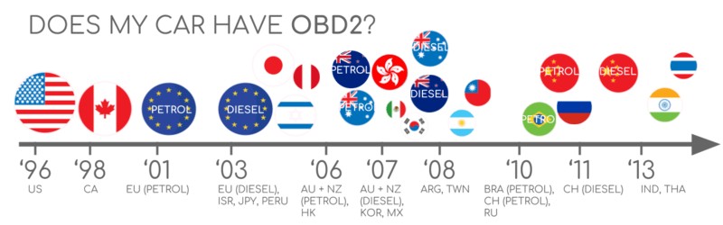
To quickly check your car’s likelihood of OBD2 compliance, consider this general guideline based on where and when it was originally purchased:
OBD2 Compliance Timeline: This chart provides a general overview of OBD2 adoption based on region and vehicle type. Always consult your vehicle’s manual for definitive information.
If you are unsure, consult your vehicle’s owner’s manual or check online resources specific to your car’s make, model, and year.
A Brief History of OBD2: From Emissions to Essential Diagnostics
The story of OBD2 begins in California, driven by the need to control vehicle emissions. The California Air Resources Board (CARB) pioneered on-board diagnostics, requiring OBD systems in new cars from 1991 onwards for emissions monitoring.
The Society of Automotive Engineers (SAE) played a crucial role in standardizing the protocol. They recommended OBD2, leading to standardized Diagnostic Trouble Codes (DTCs) and the universal OBD connector, defined by SAE J1962. This standardization was a game-changer, enabling any compatible scan tool to interface with any OBD2 compliant vehicle, regardless of manufacturer.
The rollout of OBD2 was a phased process:
- 1996: OBD2 becomes mandatory in the USA for cars and light trucks.
- 2001: The European Union mandates OBD2 for gasoline cars.
- 2004: EOBD (European On-Board Diagnostics), the EU equivalent of OBD2, becomes mandatory for diesel cars.
- 2005-2010: OBD2 mandates expand in the US to include medium and heavy-duty vehicles.
- 2008: A significant shift occurs as the ISO 15765-4 (CAN) standard becomes mandatory for OBD2 in US cars, standardizing the communication protocol to Controller Area Network (CAN bus).
OBD2’s Emission Control Origins: The initial drive for OBD2 was rooted in environmental concerns and the need to monitor and reduce vehicle emissions.
OBD2 Timeline: This visual timeline highlights the key milestones in the development and mandatory adoption of OBD2 across different regions and vehicle types.
The Future of OBD: OBD3 concepts envision remote diagnostics and integration with telematics systems, although privacy and data access remain key considerations.
The Future of OBD2: Evolution and Challenges
While OBD2 remains a cornerstone of vehicle diagnostics, its future is evolving in response to technological advancements and industry needs.
Several key trends are shaping the next chapter of OBD:
- OBD and Electric Vehicles: As mentioned earlier, the focus on emissions for traditional OBD2 means EVs often take a different approach. The rise of EVs may lead to new diagnostic standards tailored to electric powertrains and systems, potentially building upon or existing alongside OBD2.
- Advanced OBD Protocols: Protocols like WWH-OBD (World Wide Harmonized OBD) and OBDonUDS (OBD on UDS – Unified Diagnostic Services) are emerging as enhancements to address the limitations of traditional OBD2. These protocols leverage the more flexible and powerful UDS protocol for more streamlined and data-rich communication.
- OBD3 and Telematics: The concept of OBD3 envisions integrating telematics directly into vehicles, enabling remote emission monitoring and diagnostics. Imagine vehicles automatically reporting DTCs and VIN to central servers via wireless communication. While technically feasible (devices like CANedge2 and CANedge3 already facilitate data transfer via WiFi/cellular), OBD3 raises privacy concerns and faces political hurdles related to data surveillance and control.
- OEM Data Access Control: Automakers are increasingly interested in controlling access to vehicle data. Concerns around third-party access and data-driven economies built on OBD2 data are leading to discussions about potentially limiting OBD2 functionality while driving, with data being collected centrally by manufacturers instead. This could impact the aftermarket OBD2 service and device industry significantly.
EV Data Access: The future of OBD2 in electric vehicles is uncertain, with some manufacturers potentially limiting access to standard OBD2 data in favor of proprietary systems.
Deep Dive: What Information Does OBD2 Actually Provide?
Now, let’s get to the heart of the matter: what specific information does OBD2 provide? OBD2 is not just about error codes. It’s a rich source of data encompassing various aspects of your vehicle’s operation. This information can be broadly categorized as follows:
-
Diagnostic Trouble Codes (DTCs): This is perhaps the most well-known function of OBD2. DTCs are standardized codes that pinpoint specific malfunctions or issues detected by the vehicle’s computer. They cover a wide range of systems, including:
- Powertrain (P-codes): Engine and transmission related issues.
- Chassis (C-codes): Braking, suspension, and steering systems.
- Body (B-codes): Body electronics, including airbags, power windows, and central locking.
- Network/Communication (U-codes): Communication issues within the vehicle’s electronic network.
DTCs help mechanics and DIYers quickly identify the source of a problem, saving time and effort in diagnosis. OBD2 scanners can read both “pending” codes (intermittent issues) and “stored” codes (confirmed faults).
-
Real-time Parameter Identification Data (PIDs): This is where OBD2 truly shines in providing a wealth of live data. PIDs are numerical identifiers for specific vehicle parameters. OBD2 provides access to hundreds of standardized PIDs, offering a real-time window into your engine and vehicle systems. Examples of key PIDs include:
- Engine Speed (RPM): How fast your engine is turning.
- Vehicle Speed: Your current speed.
- Engine Coolant Temperature: Crucial for engine health monitoring.
- Intake Air Temperature: Affects engine performance and efficiency.
- Mass Air Flow (MAF) Rate: Measures the amount of air entering the engine.
- Throttle Position: Indicates how much the throttle is open.
- Oxygen Sensor Readings: Essential for monitoring emissions and fuel efficiency.
- Fuel Trim (Short Term & Long Term): Indicates how the engine computer is adjusting fuel delivery.
- Fuel Level: Remaining fuel in the tank.
- Battery Voltage: System voltage.
- Ignition Timing Advance: Timing of the spark plugs firing.
- Engine Load: Percentage of maximum engine power being used.
- Manifold Absolute Pressure (MAP): Pressure in the intake manifold.
This real-time data is invaluable for:
- Performance Monitoring: Observe how your engine and vehicle systems are performing under different driving conditions.
- Diagnostic Assistance: Live data can help pinpoint intermittent problems or confirm diagnoses based on DTCs.
- Fuel Efficiency Analysis: Monitor fuel consumption-related PIDs to optimize driving habits.
- Custom Dashboards and Telematics: OBD2 data is the foundation for many aftermarket gauges, performance monitors, and telematics applications.
-
Freeze Frame Data: When a DTC is set, OBD2 often stores “freeze frame” data. This is a snapshot of key PIDs at the moment the fault occurred. Freeze frame data provides valuable context, showing the engine conditions (speed, load, temperature, etc.) that were present when the problem was detected. This helps technicians recreate the fault conditions and understand the triggering factors.
-
Vehicle Identification Number (VIN): OBD2 Mode 9 allows retrieval of the vehicle identification number electronically. This can be useful for verifying vehicle identity and for certain diagnostic or telematics applications.
-
Readiness Monitors (I/M Monitors): OBD2 includes “readiness monitors” that indicate whether various emission control systems have been tested and are ready for an emissions test. These monitors track the status of components like the oxygen sensors, catalytic converter, evaporative emissions system, and more. Knowing the status of readiness monitors is crucial for passing emissions inspections.
-
Test Results (Mode 6): Mode 6 provides access to on-board diagnostic test results for specific components and systems. This is more advanced data, often used by experienced technicians for deeper diagnostics. It can show detailed pass/fail results for various tests performed by the vehicle’s computer.
-
Oxygen Sensor Test Results (Mode 5): Specifically for oxygen sensors, Mode 5 provides detailed test results that can help diagnose sensor performance and potential issues in the emissions control system.
It’s important to note that not all vehicles support every OBD2 PID or mode. The level of data available can vary depending on the vehicle manufacturer, model year, and specific ECU (Electronic Control Unit). However, the standardized PIDs and modes provide a substantial and universally accessible dataset for diagnostics and vehicle monitoring across a vast range of vehicles.
Understanding OBD2 Standards: The Foundation of Communication
OBD2’s effectiveness relies on standardized protocols and specifications. It’s not just a connector; it’s a whole system defined by standards. OBD2 operates as a higher-layer protocol, much like a language spoken over a communication network. In the automotive context, the most common communication network for OBD2 is CAN bus.
Think of it this way: CAN bus is like the phone line, providing the physical communication channel, while OBD2 is the language spoken over that line to request and interpret diagnostic information.
OBD2 standards define several key aspects:
- OBD2 Connector (SAE J1962 / ISO 15031-3): Specifies the physical 16-pin connector, its pinout, and location in the vehicle.
- Lower-Layer Protocols: Defines the communication protocols used for data transmission. While CAN bus (ISO 15765) is dominant today, older protocols like KWP2000, ISO 9141, and SAE J1850 were also used.
- OBD2 Parameter IDs (PIDs) (SAE J1979 / ISO 15031-5): Standardizes the codes (PIDs) used to request specific data parameters and defines how the data is formatted and scaled.
- Diagnostic Services (Modes) (SAE J1979 / ISO 15031-5): Defines the standardized “modes” or services for accessing different types of diagnostic information (e.g., reading DTCs, reading real-time data, clearing codes).
The relationship between OBD2 and CAN bus can be visualized using the 7-layer OSI model for network communication. OBD2 operates at the application layer (layer 7), while CAN bus covers the physical and data link layers (layers 1 and 2).
OSI Model and OBD2/CAN Bus: This diagram illustrates how OBD2 and CAN bus relate within the 7-layer OSI model for network communication. OBD2 operates at a higher layer, utilizing CAN bus as the physical and data link layer.
OBD2 Connector Pinout (Type A): This diagram shows the pinout of a standard Type A OBD2 connector, detailing the function of each pin. Note the pins for CAN bus communication (CAN-H and CAN-L) on pins 6 and 14.
The OBD2 Connector: Your Gateway to Vehicle Data
The OBD2 connector, formally specified by SAE J1962 and ISO 15031-3, is the physical interface point for accessing your car’s diagnostic system. This standardized 16-pin connector is designed for easy access and is typically located within reach of the driver’s seat.
Key features of the OBD2 connector include:
- 16 Pins: The connector has 16 pins, each with a defined function.
- Standardized Location: While generally near the steering wheel, the exact location can vary slightly by vehicle make and model. It might be visible or hidden behind a small panel.
- Power Supply: Pin 16 provides battery power, often even when the ignition is off, allowing certain diagnostic functions to operate with the engine off.
- Protocol-Specific Pinout: The specific pins used for communication depend on the lower-layer protocol employed by the vehicle. For CAN bus, pins 6 (CAN-High) and 14 (CAN-Low) are the key data communication pins.
OBD2 Connector Types: Type A vs. Type B
While most passenger cars use the Type A OBD2 connector, you might encounter the Type B connector, particularly in medium and heavy-duty vehicles.
The key differences between Type A and Type B connectors are:
- Voltage: Type A is typically 12V (cars), while Type B is 24V (trucks).
- Groove: Type B connectors have an interrupted groove in the middle, which physically prevents a Type A connector from being fully inserted.
- Baud Rate: Heavy-duty vehicles with Type B connectors often use a slower CAN bus baud rate of 250 Kbps (compared to 500 Kbps common in cars), although 500 Kbps support is increasing in newer heavy-duty vehicles.
Importantly, a Type B OBD2 adapter cable is usually designed to be compatible with both Type A and Type B sockets, whereas a Type A adapter will only fit into a Type A socket.
OBD2 Connector Types A and B: This illustration highlights the physical differences between Type A and Type B OBD2 connectors, primarily the voltage and the presence of an interrupted groove in Type B.
OBD2 and CAN Bus Relationship: This diagram reinforces the layered relationship between OBD2 as a diagnostic protocol and CAN bus as the underlying communication network, as defined by ISO 15765.
OBD2 and CAN Bus: Communication at the Core
Since 2008, CAN bus (ISO 15765-4) has been the mandatory lower-layer protocol for OBD2 in all cars sold in the US. This standardization to CAN bus is crucial for interoperability and reliable communication.
ISO 15765-4 (Diagnostics over CAN or DoCAN) defines how OBD2 messages are transmitted over a CAN bus network. It specifies key parameters:
- Bit Rate: CAN bus for OBD2 must use either 250 Kbps or 500 Kbps.
- CAN IDs: Both 11-bit (standard) and 29-bit (extended) CAN identifiers are allowed for OBD2 communication.
- Specific CAN IDs for OBD2: Certain CAN IDs are reserved for OBD2 requests and responses.
- Data Length: Diagnostic CAN frames must have a data length of 8 bytes.
- Cable Length Limit: OBD2 adapter cables are limited to a maximum length of 5 meters to ensure signal integrity.
OBD2 CAN Identifiers: Addressing and Communication Flow
OBD2 communication over CAN bus relies on a request-response model. An external tool (like a scanner) sends a request message, and the vehicle’s ECU responds with the requested data.
For 11-bit CAN identifiers, commonly used in cars:
- Functional Addressing (Request): The CAN ID 0x7DF is used for “functional requests.” This acts as a broadcast message, asking all OBD2-compliant ECUs to respond if they have data for the requested parameter.
- Physical Addressing (Request): CAN IDs in the range 0x7E0-0x7E7 are used for “physical requests,” targeting specific ECUs. This is less frequently used than functional addressing.
- Responses: ECUs respond using CAN IDs in the range 0x7E8-0x7EF. The most common response ID is 0x7E8, typically originating from the ECM (Engine Control Module). 0x7E9 often comes from the TCM (Transmission Control Module).
In some vehicles, particularly vans and medium/heavy-duty vehicles, 29-bit CAN identifiers might be used for OBD2 communication. In this case:
- Functional Addressing (Request): 0x18DB33F1 is the functional request ID.
- Responses: Responses use CAN IDs in the range 0x18DAF100 to 0x18DAF1FF, with 0x18DAF110 and 0x18DAF11E being typical examples. These response IDs are sometimes referenced in the J1939 PGN (Parameter Group Number) format, specifically PGN 0xDA00 (55808), which is designated as “Reserved for ISO 15765-2” in the J1939-71 standard.
OBD2 Request-Response Model: This diagram illustrates the fundamental request-response communication flow in OBD2. A diagnostic tool sends a request, and the vehicle’s ECU responds with the requested data.
OBD2 vs. Proprietary CAN: This diagram highlights the distinction between standardized OBD2 communication and manufacturer-specific, proprietary CAN bus data within a vehicle. OBD2 is an “extra” protocol operating alongside the OEM’s internal communication network.
OBD2 vs. Proprietary CAN Protocols: Two Worlds of Data
It’s crucial to understand that your car’s internal systems and ECUs do not rely on OBD2 for their core functions. Automakers implement their own proprietary CAN protocols for internal communication between ECUs, sensor data exchange, and vehicle control. These proprietary protocols are specific to the vehicle brand, model, and year, and their data formats are typically not publicly documented.
OBD2 is essentially an additional, standardized higher-layer protocol that sits alongside the OEM’s proprietary CAN network. When you connect an OBD2 scanner, you are specifically interacting with the OBD2 system, not necessarily directly accessing the deeper, proprietary CAN data used for the car’s core operations.
In many newer vehicles, a “gateway” module acts as a security barrier, isolating the OBD2 port and communication from the more sensitive OEM-specific CAN data. This gateway allows OBD2 communication for diagnostics but prevents direct access to the potentially more detailed and control-oriented proprietary data.
Think of OBD2 as a publicly accessible “diagnostic window” into certain aspects of your car’s health and emissions, while the OEM’s proprietary CAN network represents the car’s internal “nervous system” used for its fundamental operation.
Validating Communication: Bit-Rate and ID Checks
Given the potential variations in bit rates (250K or 500K) and CAN ID lengths (11-bit or 29-bit), diagnostic tools need a way to automatically detect the correct communication parameters for a given vehicle.
ISO 15765-4 provides a recommended initialization sequence to determine the appropriate combination. This process leverages a mandatory OBD2 service (Mode 0x01 PID 0x00 – “Supported PIDs”) that all OBD2-compliant vehicles must support.
The validation process typically involves:
- Bit-Rate Testing: The tool attempts to transmit a CAN frame at a default bit rate (e.g., 500 Kbps). If successful (no CAN error frames), it confirms that bit rate. If unsuccessful, it tries the alternative bit rate (e.g., 250 Kbps).
- “Supported PIDs” Request: Once the bit rate is established, the tool sends a “Supported PIDs” request (Mode 0x01 PID 0x00).
- Response Analysis: The vehicle’s response to the “Supported PIDs” request helps determine:
- CAN ID Length: Based on the response IDs (e.g., 0x7E8 range for 11-bit, 0x18DAF1xx range for 29-bit).
- Supported PIDs: The data payload in the response indicates which PIDs (within the 0x01-0x20 range initially, and further ranges with subsequent requests) are supported by the vehicle.
OBD2 Bit-Rate and CAN ID Validation Flow: This flowchart outlines the systematic process defined in ISO 15765-4 for automatically validating the correct bit rate and CAN ID format for OBD2 communication with a vehicle.
OBD2 Lower-Layer Protocols: While CAN bus (ISO 15765) is dominant today, this diagram illustrates the five lower-layer protocols that have been used for OBD2 communication, including older standards like KWP2000, ISO 9141, and SAE J1850.
Legacy Protocols: Beyond CAN Bus
While CAN bus (ISO 15765) is the predominant lower-layer protocol for OBD2 today, especially in vehicles from 2008 onwards, older cars might utilize different protocols. It’s helpful to be aware of these legacy protocols, especially when working with pre-2008 vehicles:
- ISO 15765 (CAN bus): The current standard, mandatory in US cars since 2008 and widely used globally.
- ISO 14230-4 (KWP2000 – Keyword Protocol 2000): Common in early 2000s cars, particularly in Asia and some European models.
- ISO 9141-2: Used in European, Chrysler, and Asian cars from the late 1990s to early 2000s.
- SAE J1850 VPW (Variable Pulse Width Modulation): Primarily used in older General Motors (GM) vehicles.
- SAE J1850 PWM (Pulse Width Modulation): Mainly found in older Ford vehicles.
The OBD2 connector pinout can sometimes offer clues about the protocol used in older cars, as different protocols might utilize different pins for communication.
ISO-TP: Transporting OBD2 Messages Beyond 8 Bytes
OBD2 data communication over CAN bus uses a transport protocol called ISO-TP (ISO 15765-2). This protocol is essential because it allows for the transmission of data payloads larger than the standard 8-byte limit of a CAN frame.
ISO-TP enables multi-frame communication, where a single logical OBD2 message is broken down into multiple CAN frames for transmission and then reassembled at the receiving end. This is necessary for OBD2 services that require larger data payloads, such as:
- Retrieving the Vehicle Identification Number (VIN): The VIN is longer than 8 bytes.
- Reading Diagnostic Trouble Codes (DTCs): When multiple DTCs are present, the total data can exceed 8 bytes.
- Some Mode 6 Test Results: Detailed test results might require multi-frame messages.
ISO-TP handles:
- Segmentation: Dividing large OBD2 messages into smaller segments that fit within CAN frames.
- Flow Control: Mechanisms to manage the flow of multi-frame messages, ensuring reliable transmission and preventing buffer overflows.
- Reassembly: Reconstructing the complete OBD2 message from the received CAN frame segments.
For simpler OBD2 requests and responses where the data fits within a single CAN frame, ISO-TP still plays a role. In these “Single Frame” (SF) transmissions, the first byte of the CAN data payload (the PCI – Protocol Control Information field) indicates the payload length, leaving up to 7 bytes for the actual OBD2 data.
ISO-TP Frame Types for OBD2: This diagram illustrates the different types of CAN frames used in ISO-TP for OBD2 communication, including Single Frame (SF), First Frame (FF), Consecutive Frame (CF), and Flow Control (FC) frames, enabling the transport of OBD2 messages larger than 8 bytes.
Decoding the OBD2 Diagnostic Message: Structure and Examples
To understand the practicalities of what information OBD2 provides, let’s examine the structure of a typical OBD2 diagnostic message transmitted over CAN bus.
In a simplified “Single Frame” OBD2 message, the structure is as follows:
- CAN Identifier: (e.g., 0x7DF for functional request, 0x7E8 for ECM response).
- Data Length (PCI Field): First byte of the CAN data payload, indicating the length of the OBD2 data.
- OBD2 Data: The remaining bytes in the CAN data payload, containing:
- Mode (Service ID): Specifies the OBD2 service being requested or responded to (e.g., 0x01 for “Show current data”).
- Parameter ID (PID): Identifies the specific parameter being requested or reported within the chosen mode (e.g., 0x0D for vehicle speed).
- Data Bytes: The actual data values for the requested parameter, encoded according to the PID definition.
OBD2 Message Structure: This diagram breaks down the structure of a raw OBD2 CAN message, highlighting the key components: CAN ID, PCI field (data length), Mode (Service ID), PID, and Data Bytes.
Example: Requesting and Receiving Vehicle Speed (PID 0x0D)
Let’s illustrate with a practical example: requesting and receiving vehicle speed (PID 0x0D) using OBD2 Mode 0x01 (“Show current data”).
Request Message:
- CAN ID: 0x7DF (Functional Request)
- Data Payload:
- Byte 1 (PCI): 0x02 (Data length is 2 bytes)
- Byte 2 (Mode): 0x01 (Service 0x01: Show current data)
- Byte 3 (PID): 0x0D (PID 0x0D: Vehicle Speed)
Response Message (from ECM):
- CAN ID: 0x7E8 (ECM Response)
- Data Payload:
- Byte 1 (PCI): 0x03 (Data length is 3 bytes)
- Byte 2 (Mode + 0x40): 0x41 (Response to Service 0x01)
- Byte 3 (PID): 0x0D (PID 0x0D: Vehicle Speed)
- Byte 4 (Data): 0x32 (Example speed value in km/h)
In this example, the request asks for vehicle speed (PID 0x0D) using Mode 0x01. The car’s ECM responds with the speed value. To interpret the speed value (0x32 in hex, which is 50 in decimal), you need to consult the OBD2 PID documentation (SAE J1979 or ISO 15031-5) to understand the scaling and units for PID 0x0D (typically km/h).
OBD2 Request and Response Example (Vehicle Speed): This diagram shows the CAN frames for a request for vehicle speed (PID 0x0D) and the corresponding response, highlighting the CAN IDs, Mode, and PID values.
OBD2 PID 0x0D (Vehicle Speed) Details: This illustrates how OBD2 PID 0x0D, vehicle speed, is encoded in the data payload and how to decode it to a physical value (km/h).
OBD2 Services (Modes): This diagram provides an overview of the 10 standardized OBD2 diagnostic services (modes), ranging from reading real-time data (Mode 0x01) to clearing DTCs (Mode 0x04).
The 10 OBD2 Services (Modes): Accessing Different Diagnostic Information
OBD2 defines 10 standardized diagnostic services, also known as modes. Each mode provides access to a different category of diagnostic information:
- Mode 0x01: Show current data: Requests real-time parameter data (PIDs).
- Mode 0x02: Show freeze frame data: Retrieves freeze frame data for a specific DTC.
- Mode 0x03: Show stored Diagnostic Trouble Codes: Reads currently stored DTCs.
- Mode 0x04: Clear Diagnostic Trouble Codes and stored values: Clears DTCs and resets related system values (use with caution!).
- Mode 0x05: Oxygen sensor monitoring test results: Retrieves results from on-board oxygen sensor tests.
- Mode 0x06: On-board monitoring test results for non-continuously monitored systems: Accesses test results for systems not continuously monitored.
- Mode 0x07: Show pending Diagnostic Trouble Codes: Reads DTCs that are detected intermittently but not yet confirmed as faults.
- Mode 0x08: Control operation of on-board component/system: Allows for bi-directional control of certain on-board systems (less commonly used in basic OBD2 scanners).
- Mode 0x09: Request vehicle information: Retrieves vehicle information like VIN and calibration IDs.
- Mode 0x0A: Show permanent Diagnostic Trouble Codes: Reads DTCs that cannot be cleared by simply using Mode 0x04 (permanent DTCs).
Vehicles are not required to support all 10 OBD2 modes. The level of mode support varies by manufacturer and model. Additionally, some manufacturers may implement OEM-specific modes beyond the 10 standardized modes for more advanced diagnostics.
In OBD2 messages, the mode is indicated in the second byte of the data payload in a request message. In a response message, 0x40 is added to the mode value to distinguish it as a response (e.g., a response to Mode 0x01 will have Mode value 0x41 in the response).
OBD2 Parameter IDs (PIDs): The Data Dictionary
Within each OBD2 mode, Parameter IDs (PIDs) are used to request specific data points. Mode 0x01 (“Show current data”) has a particularly extensive list of standardized PIDs, numbering around 200. These PIDs cover a wide range of real-time data parameters, as discussed earlier.
However, it’s important to remember that vehicles do not have to support all standardized OBD2 PIDs. In practice, most vehicles only support a subset of the available PIDs within each mode.
One PID stands out as particularly important for OBD2 compatibility testing: Mode 0x01 PID 0x00 (“Supported PIDs [01-20]”). If an emissions-related ECU supports any OBD2 services at all, it must support Mode 0x01 PID 0x00. Responding to this PID, the ECU reports which PIDs in the range 0x01-0x20 it supports. This makes PID 0x00 a fundamental “OBD2 compatibility test.” Similarly, PIDs 0x20, 0x40, 0x60, 0x80, 0xA0, and 0xC0 are used to determine support for subsequent PID ranges within Mode 0x01.
OBD2 PIDs in Request-Response Frames: This diagram reiterates how PIDs are used within OBD2 request and response messages to specify the particular parameter being requested or reported.
OBD2 PID Overview Tool: Tools like this online PID lookup can be invaluable for understanding OBD2 PIDs, their descriptions, scaling, and units, aiding in the interpretation of OBD2 data.
OBD2 PID Overview Tools and Resources
To effectively work with OBD2 data, you need access to information about the standardized PIDs, their meanings, scaling, units, and decoding methods. The official sources for this information are the appendices of SAE J1979 and ISO 15031-5.
However, for convenience, various online resources and tools are available to help you look up OBD2 PIDs. These tools often provide:
- PID Descriptions: Clear explanations of what each PID represents.
- Scaling and Units: Information on how to convert the raw data bytes into physical values (e.g., km/h, degrees Celsius, RPM).
- Formulae: Mathematical formulas for decoding the data.
- Supported Modes: Which OBD2 modes the PID is associated with.
Using an OBD2 PID overview tool or referencing PID documentation is essential for accurately interpreting the raw data you retrieve from your vehicle’s OBD2 system.
OBD2 PID overview tool
Online OBD2 PID Lookup Tool: This link leads to an example of a web-based OBD2 PID lookup tool, which simplifies the process of finding information about specific PIDs.
Practical OBD2 Data Logging and Decoding: A Step-by-Step Guide
Let’s move from theory to practice and outline how you can actually log and decode OBD2 data. We’ll use the CANedge CAN bus data logger as an example, but the general principles apply to other OBD2 logging and analysis tools.
The basic steps are:
- Test Bit-Rate, IDs, and Supported PIDs: Establish communication with your vehicle and determine the correct CAN bus bit rate, CAN ID format, and supported OBD2 PIDs.
- Configure OBD2 PID Requests: Set up your data logger to send requests for the specific PIDs you want to record.
- DBC Decode Raw OBD2 Data: Use a DBC (CAN database) file to decode the raw CAN data into human-readable physical values.
OBD2 Data Logger Connection: Connecting an OBD2 data logger, like the CANedge, to a vehicle’s OBD2 port enables the recording of valuable diagnostic and performance data.
Bit-Rate Validation: Before starting OBD2 data logging, it’s crucial to validate the correct CAN bus bit rate for communication with the vehicle. This screenshot shows an example of a bit-rate validation test.
Supported PIDs Test: Testing for supported PIDs helps determine which data parameters are available from the vehicle’s OBD2 system. This screenshot shows responses to “Supported PIDs” requests in asammdf software.
Step #1: Bit-Rate, ID, and Supported PID Validation
As discussed earlier, ISO 15765-4 outlines a process for automatically validating the bit rate and CAN ID format. You can replicate this process using a CANedge or similar tool:
- Bit-Rate Test: Configure your data logger to transmit a CAN frame at 500 Kbps. Monitor for successful transmission (no CAN error frames). If unsuccessful, try 250 Kbps.
- “Supported PIDs” Requests: Send multiple “Supported PIDs” requests (Mode 0x01 PID 0x00) using functional addressing (CAN ID 0x7DF for 11-bit IDs).
- Analyze Responses: Review the responses in your CAN analysis software (e.g., asammdf).
- CAN IDs: Observe the response CAN IDs (e.g., 0x7E8, 0x7E9) to confirm 11-bit IDs are being used (or look for 29-bit IDs if expected).
- Data Payload: Examine the data bytes in the responses. The response to PID 0x00 indicates which PIDs in the 0x01-0x20 range are supported. You’ll need to decode this binary data (bitmask) to determine the supported PIDs. Use an OBD2 PID lookup tool to interpret the bitmask.
- Response Count: You might see multiple responses to a single functional request (0x7DF) because multiple ECUs might be OBD2 compliant and respond.
Step #2: Configure OBD2 PID Requests for Logging
Once you know the supported PIDs and communication parameters, configure your data logger to continuously request the PIDs you want to log.
Consider these points when configuring PID requests:
- CAN IDs: For logging, you can often switch to “Physical Addressing” (e.g., request ID 0x7E0 for the ECM) to target a specific ECU and reduce bus traffic if you are primarily interested in data from a particular module.
- Request Spacing: Avoid “spamming” the ECUs with requests. Introduce a delay (e.g., 300-500 milliseconds) between consecutive OBD2 requests to ensure reliable responses.
- Battery Drain: If logging with the ignition off, be mindful of battery drain. Use triggers or power management features in your data logger to stop logging when the vehicle is inactive.
- Filtering: If your vehicle also outputs OEM-specific CAN data alongside OBD2, set up filters in your data logger to record only the relevant OBD2 response CAN IDs (e.g., 0x7E8-0x7EF) to focus on the diagnostic data.
OBD2 Transmit List Example: This screenshot shows an example configuration of an OBD2 transmit list in a CANedge data logger, defining the PIDs to request and the request intervals.
Decoded and Visualized OBD2 Data: After logging, OBD2 data can be decoded using a DBC file and visualized in software like asammdf, allowing for analysis of vehicle parameters over time.
Step #3: DBC Decoding and Data Analysis
To make sense of the raw OBD2 data you’ve logged, you need to decode it into physical values. This is where a DBC file comes in. A DBC file is a CAN database file that contains the decoding rules for CAN messages and signals.
For OBD2, you can use a generic OBD2 DBC file (many are available online, including a free one provided by the CANedge manufacturer). This DBC file will contain definitions for the standardized OBD2 PIDs, including their scaling, units, and data types.
However, OBD2 decoding is slightly more complex than standard CAN signal decoding. Because different OBD2 PIDs are transmitted using the same CAN IDs (e.g., all ECM responses might use CAN ID 0x7E8), simply filtering by CAN ID is not enough to identify the specific signal.
OBD2 utilizes a form of extended multiplexing. To decode OBD2 data correctly, your DBC file and CAN analysis software need to consider:
- CAN ID: (e.g., 0x7E8).
- OBD2 Mode: (e.g., 0x41 for Mode 0x01 response).
- OBD2 PID: (e.g., 0x0D for vehicle speed).
The DBC file will contain logic to combine these three pieces of information to uniquely identify and decode each OBD2 signal within the data stream. Modern CAN analysis tools like asammdf support this extended multiplexing and can correctly decode OBD2 data using a suitable DBC file.
CANedge: OBD2 data logger
CANedge OBD2 Data Logger: The CANedge is a robust and versatile data logger suitable for recording OBD2 data, offering features like SD card logging, configurable CAN channels, and compatibility with various analysis tools.
OBD2 logger intro
OBD2 Data Logger Introduction: This link provides further information about OBD2 data loggers and their applications in vehicle diagnostics and data analysis.
OBD2 Multi-Frame Communication Examples: VIN, Multi-PID Requests, and DTCs
Most of the examples so far have focused on single-frame OBD2 communication. However, as discussed earlier, ISO-TP enables multi-frame communication for larger OBD2 messages. Let’s look at some examples of multi-frame OBD2 services:
OBD2 Multi-Frame Request (VIN): This diagram shows a request message for the Vehicle Identification Number (VIN), which typically requires multi-frame communication due to the VIN’s length.
Example 1: Retrieving the Vehicle Identification Number (VIN)
To retrieve the VIN using OBD2, you use Mode 0x09 (“Request vehicle information”) and PID 0x02 (“Vehicle Identification Number”).
The communication flow is multi-frame because the VIN is longer than 7 data bytes (the effective payload in a single-frame message).
- Request: The diagnostic tool sends a single-frame request for Mode 0x09 PID 0x02.
- Response: The vehicle responds with a multi-frame response using ISO-TP. This response typically includes:
- First Frame (FF): Indicates the total length of the VIN data and the start of the VIN payload.
- Consecutive Frames (CFs): Contain subsequent segments of the VIN data.
- Flow Control (FC) frames: Used for flow control in ISO-TP, although in many OBD2 implementations, a static flow control frame can be used.
The VIN data in the multi-frame response is typically encoded in ASCII (or a similar character encoding). You’ll need to reassemble the multi-frame payload and convert the HEX values to ASCII characters to get the readable VIN string.
Example 2: Multi-PID Request (Requesting up to 6 PIDs at Once)
OBD2 allows for requesting up to 6 Mode 0x01 PIDs in a single request frame. The ECU will respond with data for the supported PIDs from the request (unsupported PIDs are omitted from the response). If the response data exceeds 7 bytes, it will be sent as a multi-frame response using ISO-TP.
This multi-PID request feature can improve data acquisition efficiency by reducing the number of request frames needed. However, it also complicates decoding because the order and presence of PIDs in the response payload are dependent on the specific PIDs requested and which ones are supported by the vehicle. Generic OBD2 DBC files might not readily handle this type of multiplexed response.
Example 3: Retrieving Diagnostic Trouble Codes (DTCs)
To retrieve emissions-related DTCs, you use Mode 0x03 (“Show stored Diagnostic Trouble Codes”). No PID is included in the request for this mode.
The ECU responds with a multi-frame message if there are more than a few DTCs stored (as each DTC is typically 2 bytes). The response payload indicates the number of DTCs and then lists the DTC codes.
Each DTC code is 2 bytes and needs to be decoded according to ISO 15031-5/ISO 15031-6. The first two bits of the first byte define the DTC category (Powertrain, Chassis, Body, Network), and the remaining 14 bits form a 4-digit hexadecimal code. You can use online OBD2 DTC lookup tools to translate these codes into descriptive error messages (e.g., repairpal.com).
OBD2 DTC Decoding: This diagram illustrates how a 2-byte DTC code is structured and how to decode it to determine the DTC category and the 4-digit hexadecimal code. Online DTC lookup tools are then used to find the description of the code.
OBD2 Data Logging Use Cases: Unlocking Value from Vehicle Data
The wealth of information provided by OBD2 opens up a wide range of applications. OBD2 data logging is valuable for:
Logging data from cars
OBD2 data from cars can be used for diverse purposes, including:
- Fuel Efficiency Optimization: Analyze fuel consumption data to identify driving habits that waste fuel and improve efficiency.
- Driver Behavior Monitoring: Track driving parameters like speed, acceleration, and braking patterns for fleet management, insurance telematics, or driver training.
- Performance Analysis: Record engine parameters during track days or performance tuning to assess vehicle performance and make adjustments.
- Prototype Testing: Log OBD2 data from vehicles equipped with prototype parts or systems to evaluate their performance and identify potential issues.
- Insurance Telematics: OBD2 data forms the basis for usage-based insurance programs, where premiums are adjusted based on driving behavior and mileage.
obd2 logger
OBD2 Data Logger Applications: OBD2 data loggers are versatile tools for various applications, including fuel efficiency analysis, driver behavior monitoring, and vehicle performance assessment.
Real-time Car Diagnostics
OBD2 interfaces enable real-time streaming of diagnostic data for:
- Live Diagnostics: Mechanics and DIYers can use OBD2 scanners to monitor live data while troubleshooting vehicle issues, providing immediate feedback and helping pinpoint problems faster.
- Custom Dashboards: Real-time OBD2 data can be displayed on custom dashboards or gauges, providing drivers with immediate insights into vehicle performance and health.
- Performance Monitoring: Track real-time engine parameters during driving for performance enthusiasts or for monitoring vehicle health during demanding conditions.
obd2 streaming
Real-Time OBD2 Streaming: OBD2 interfaces allow for real-time streaming of diagnostic data, enabling live diagnostics, custom dashboards, and performance monitoring applications.
Predictive Maintenance
Combining OBD2 data with IoT (Internet of Things) technologies enables:
- Remote Vehicle Monitoring: Fleet managers and vehicle owners can remotely monitor vehicle health and performance via cloud-connected OBD2 loggers.
- Predictive Maintenance: By analyzing trends in OBD2 data (e.g., sensor readings, DTC frequency), potential breakdowns or maintenance needs can be predicted, allowing for proactive maintenance and reducing downtime.
- Vehicle Health Alerts: Real-time alerts can be triggered based on OBD2 data anomalies, notifying drivers or fleet managers of potential issues before they escalate.
predictive maintenance
OBD2 for Predictive Maintenance: OBD2 data, when combined with IoT and cloud technologies, facilitates predictive maintenance, enabling remote vehicle monitoring and proactive maintenance scheduling.
Vehicle Black Box Logging
OBD2 loggers can serve as “black boxes” for vehicles, recording data for:
- Accident Reconstruction: OBD2 data recorded during and around an accident can provide valuable insights for accident analysis and reconstruction.
- Warranty and Dispute Resolution: Logged OBD2 data can provide objective evidence in warranty claims or disputes related to vehicle performance or malfunctions.
- Equipment Monitoring: For vehicles used in commercial or industrial applications, OBD2 logging can track equipment usage, operating conditions, and potential misuse.
can bus blackbox
OBD2 as a Vehicle “Black Box”: OBD2 data loggers can function as vehicle “black boxes,” recording data for accident reconstruction, warranty purposes, and equipment monitoring.
Do you have an OBD2 data logging use case? Reach out for free sparring!
Contact us
For more intros, see our guides section – or download the ‘Ultimate Guide’ PDF.
Need to log/stream OBD2 data?
Get your OBD2 data logger today!
Buy now Contact us
Recommended for you
OBD2 DATA LOGGER: EASILY LOG & CONVERT OBD2 DATA
CANEDGE2 – PRO CAN IoT LOGGER
[