For automotive enthusiasts, DIYers, and makers, accessing real-time vehicle data opens up a world of possibilities. The Obd2 Ttl Adapter serves as the key to unlocking this data, acting as a bridge between your car’s On-Board Diagnostics (OBD) port and the versatile Arduino platform. This guide delves into the functionalities, features, and applications of the OBD2 TTL adapter, empowering you to tap into your vehicle’s information for innovative projects and insightful diagnostics.
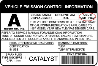 OBD-II certification sticker indicating vehicle compliance
Key Features of the OBD2 TTL Adapter
This compact yet powerful adapter is engineered to provide seamless access to your vehicle’s internal network, offering a range of features that make it an invaluable tool for automotive hacking and diagnostics:
- Comprehensive OBD-II PID Access: Leveraging the widely adopted ELM327 AT command set, the adapter grants access to all standard OBD-II Parameter IDs (PIDs). This allows you to retrieve a vast array of real-time data points from your vehicle’s engine and systems.
- Diagnostic Trouble Code (DTC) Reading and Clearing: Effortlessly read and clear engine and powertrain Diagnostic Trouble Codes. This feature is crucial for understanding and addressing vehicle issues, allowing for proactive maintenance and troubleshooting.
- CAN Bus Sniffing Capability: Dive deep into your vehicle’s communication network with CAN bus sniffing. This advanced feature enables you to monitor and analyze Controller Area Network (CAN) bus traffic, providing insights into vehicle system interactions.
- Real-time Car Battery Voltage Monitoring: Keep track of your car battery’s health with built-in voltage measurement. Monitoring voltage is essential for preventing battery-related issues and ensuring reliable vehicle operation.
- Integrated 9-DOF Motion Sensing: Equipped with an MPU-9250 9-DOF motion sensor, the adapter detects motion and orientation. This opens doors to applications involving vehicle dynamics analysis, tilt sensing, and more.
- Orientation Measurement with Sensor Fusion: The built-in quaternion sensor fusion algorithm processes motion sensor data to provide accurate orientation measurements. This advanced capability is valuable for projects requiring precise vehicle orientation tracking.
- Versatile 5V Power Supply: The adapter, powered directly from the OBD port, provides a regulated 5V/2.1A power output. This eliminates the need for external power sources for your Arduino and connected devices, simplifying project setup.
- Serial UART Compatibility: Featuring serial UART compatibility with both 3.3V and 5V microcontrollers, the adapter seamlessly integrates with a wide range of Arduino boards and other embedded systems.
- Micro USB Connectivity: A Micro USB port allows for direct connection to computers or tablets. This facilitates data logging, configuration, and interaction with the adapter from a computer environment.
- Dedicated Arduino Library and Examples: A readily available open-source Arduino library, complete with example sketches, streamlines development and accelerates project implementation. This library simplifies accessing the adapter’s features and functionalities within the Arduino ecosystem.
Vehicle Compatibility: Ensuring a Proper Connection
The OBD2 TTL adapter is designed for vehicles that are OBD-II compliant. OBD-II is a standard in most cars manufactured after 1996 in the USA and later in other regions. To verify your vehicle’s OBD-II certification, locate the sticker under the hood, often near the radiator or on the underside of the hood itself. This sticker will explicitly state “OBD-II Certified.”
The adapter supports a wide array of vehicle communication protocols, ensuring compatibility with various makes and models:
- CAN 500Kbps/29bit
- CAN 500Kbps/11bit
- CAN 250Kbps/29bit
- CAN 250Kbps/11bit
- KWP2000 Fast
- KWP2000 5Kbps
Understanding the Connectors: Power and Data Lines
The OBD2 TTL adapter plugs directly into your vehicle’s OBD port, typically located beneath the steering column or slightly to the left. A cable extending from the adapter provides clearly labeled connectors for power and data, simplifying connection to your Arduino.
Power Connector (2-pin 2.54 Dupont)
- Red Wire (VCC): Connect to the 5V pin on your Arduino.
- Black Wire (GND): Connect to the GND pin on your Arduino.
Serial UART Data Connector (2-pin 2.54 Dupont)
- White Wire (Rx): Connect to the Tx (transmit) pin of your Arduino’s serial interface.
- Green Wire (Tx): Connect to the Rx (receive) pin of your Arduino’s serial interface.
Note: For Arduino UNO or Nano, which have a single hardware serial port shared with the USB connection, avoid using serial output when the adapter is connected to the hardware serial. Arduino Leonardo, Mega, and Due, with multiple hardware serial ports, do not have this limitation.
USB Port
- The Micro USB port provides an alternative connection method for interfacing with computers or tablets using a micro USB cable.
- It also functions as a 5V/2A power output source.
Extended AT Command Set: Advanced Control and Data Access
Beyond the standard ELM327 command set, this OBD2 TTL adapter offers extended AT commands, unlocking advanced functionalities:
Motion Sensor Access Commands
- ATACL: Retrieves accelerometer data in G-force units (X, Y, Z).
- ATGYRO: Reads gyroscope data in degrees per second (X, Y, Z).
- ATMAG: Accesses magnetometer data in milli-Gauss (X, Y, Z).
- ATTEMP: Reads raw temperature data from the sensor.
Quaternion Control and Orientation Commands
- ATQU0 / ATQU1: Disables or enables the 9-DOF sensor fusion algorithm (disabled by default).
- ATORI: Retrieves orientation parameters (roll, pitch, yaw) in degrees, calculated by the 9-DOF sensor fusion.
K-Line and ISO9141-2 Specific Commands
- ATSH: Sets header bytes for communication. Example:
ATSH C1 33 F1. - ATPTH: Sets the initializing pulse time in hexadecimal (range 0-255ms). Example:
ATPTH 19(sets to 25ms). - ATPTA: Sets the negative pulse duration before the first data byte in hexadecimal (range 0-255ms). Example:
ATPTA 32(sets to 50ms).
CAN Bus Specific Commands (CAN Bus Sniffing)
- ATSH: Sets the CAN message header for 11-bit CAN. Example:
ATSH 7DF. - ATSH: Sets the lower 24 bits of the CAN message header for 29-bit CAN (higher 5 bits set by ATCP). Example:
ATSH DB 33 F1. - ATCP: Sets CAN priority/higher 5 bits of the header for 29-bit CAN. Example:
ATCP 18. - ATCF
or ATCF : Sets the CAN message header filter for CAN sniffing.<header>for 11-bit CAN,<extended header>for 29-bit CAN. Example:ATCF 7E8. - ATCM : Sets the CAN message filtering bit mask (32-bit). Example:
ATCM FFFFFFFE(ignores the lowest bit during header filtering). - ATM1: Starts CAN sniffing mode.
- ATM0: Stops CAN sniffing mode.
CAN Sniffing Examples:
11-bit 500kbps CAN bus Sniffing:
ATSP6
ATCF 700
ATCM FFFFFF00
ATM1
29-bit 500kbps CAN bus Sniffing:
ATSP7
ATCF 18DBF133
ATCM FF000000
ATM1
Arduino Library: Simplifying Integration
To streamline development, a dedicated Arduino library is provided. This library encapsulates many of the adapter’s functionalities into easy-to-use APIs, simplifying access to OBD-II data and sensor readings within your Arduino sketches. While not all AT commands are directly available as API functions, the library covers commonly used features.
Commonly Used Arduino Library APIs:
setBaudRate(): Configures the adapter’s serial baud rate.readPID(PID, value): Reads a specified OBD-II PID and returns the parsed value.clearDTC(): Clears stored Diagnostic Trouble Codes.getVoltage(): Measures the car battery voltage.getVIN(): Retrieves the Vehicle Identification Number.getTemperature(): Gets the adapter’s internal temperature.readAccel(x, y, z): Reads accelerometer X, Y, and Z axis values.memsInit(): Initializes the motion sensor.memsRead(): Reads raw motion sensor data.memsOrientation(roll, pitch, yaw): Retrieves computed orientation data (roll, pitch, yaw).
Example Arduino Code: Engine RPM Indicator
This simple example demonstrates how to use the library to create an engine RPM indicator using the built-in LED on Arduino pin 13:
#include <obd2uart.h>

COBD obd;

void setup() {
  // Configure pin 13 as output for the LED
  pinMode(13, OUTPUT);
  // Start serial communication
  obd.begin();
  // Initialize OBD-II connection until successful
  while (!obd.init());
}

void loop() {
  int value;
  // Read engine RPM and store in 'value', returns true if successful
  if (obd.readPID(PID_RPM, value)) {
    // Turn LED on if RPM exceeds 3000, otherwise turn it off
    digitalWrite(13, value > 3000 ? HIGH : LOW);
  }
}
Explore more example sketches within the Arduino OBD library repository for further inspiration and practical implementations.
Commonly Used PIDs (Parameter IDs) Defined in the OBD Library:
Engine Related PIDs:
PID_RPM: Engine RPM (revolutions per minute)PID_ENGINE_LOAD: Calculated engine load (percentage)PID_COOLANT_TEMP: Engine coolant temperature (degrees Celsius)PID_ABSOLUTE_ENGINE_LOAD: Absolute Engine load (percentage)PID_TIMING_ADVANCE: Ignition timing advance (degrees)PID_ENGINE_OIL_TEMP: Engine oil temperature (degrees Celsius)PID_ENGINE_TORQUE_PERCENTAGE: Engine torque percentage (percentage)PID_ENGINE_REF_TORQUE: Engine reference torque (Newton meters)
Intake/Exhaust Related PIDs:
PID_INTAKE_TEMP: Intake air temperature (degrees Celsius)PID_INTAKE_PRESSURE: Intake manifold absolute pressure (kilopascals)PID_MAF_FLOW: Mass Air Flow sensor reading (grams per second)PID_BAROMETRIC: Barometric pressure (kilopascals)
Speed/Time Related PIDs:
PID_SPEED: Vehicle speed (kilometers per hour)PID_RUNTIME: Engine running time (seconds)PID_DISTANCE: Vehicle running distance (kilometers)
Driver Related PIDs:
PID_THROTTLE: Throttle position (percentage)PID_AMBIENT_TEMP: Ambient temperature (degrees Celsius)
Electric Systems Related PIDs:
PID_CONTROL_MODULE_VOLTAGE: Vehicle control module voltage (Volts)PID_HYBRID_BATTERY_PERCENTAGE: Hybrid battery pack remaining life (percentage)
You can extend the library by adding definitions for any of the OBD-II PIDs supported by your vehicle’s Engine Control Unit (ECU).
Product Comparison: OBD-II UART Adapter Models
| Features | OBD-II UART Adapter V1 | OBD-II UART Adapter V2 | OBD-II UART Adapter V2.1 |
|---|---|---|---|
| Connection Cable | Fixed | Fixed | Unpluggable |
| Additional Interface | N/A | micro USB | micro USB |
| Motion Sensor | N/A | 6-DOF MPU-6050 | 9-DOF MPU-9250 |
| Voltmeter | Yes | Yes | Yes |
| Max. Output Power | 2A | 2.1A | 2.1A |
| Standby Mode Power | 5mA | 6mA | 6mA |
Frequently Asked Questions (FAQ)
Q: What are the primary applications of the OBD2 TTL adapter?
A: The adapter’s most direct application is enabling Arduino to easily access vehicle data. This capability is fundamental for creating open-source vehicle data loggers (as seen in data logger kits) and developing interactive applications that utilize real-time car data.
Q: How is the adapter powered?
A: The adapter draws power directly from the 12V DC supply provided by the OBD-II port, eliminating the need for external power connections.
Q: Does my Arduino require a separate power source when using this adapter?
A: No. The adapter includes a regulated 5V output specifically designed to power your Arduino and other connected devices. This integrated power supply simplifies wiring and project setup.
Q: Is a CAN bus shield necessary to use this adapter?
A: Absolutely not. The OBD2 TTL adapter internally handles the complexities of CAN bus communication. It retrieves data from the CAN bus, similar to a CAN bus shield, and converts it into a simpler serial UART interface that Arduino and most embedded systems can readily access. Data connection is established through the adapter’s dedicated Rx and Tx data connector pins.
Q: How do I physically connect the adapter to my Arduino board?
A: The adapter is compatible with all Arduino models. Connection involves linking the adapter’s Tx pin to Arduino’s Rx (D0) and the adapter’s Rx pin to Arduino’s Tx (D1). For convenience and ease of connection/disconnection, using an I/O breakout shield or an Arduino board with breakout pins for Rx/Tx/VCC/GND is recommended.
Q: Is the power supplied by the adapter continuously available, even when the car is off?
A: This behavior varies depending on the vehicle. In many cars, the OBD-II port remains powered even after the ignition is turned off.
Q: What is the maximum data polling frequency achievable with this adapter?
A: The OBD-II PIDs are polled sequentially. The polling time is influenced by the speed of the vehicle’s ECU and the ECU’s processing load at any given moment. In typical modern CAN bus equipped vehicles, polling times can be as low as 10 milliseconds, potentially allowing for up to 100 data polls per second.
Q: Can you provide assistance with Arduino programming challenges I might encounter?
A: While we focus on the adapter’s functionality, comprehensive Arduino programming support is beyond our scope. However, numerous online resources, guides, and tutorials are readily available to assist with Arduino programming.
Q: What distinguishes product version from firmware version?
A: The Freematics OBD-II UART Adapter V2 utilizes firmware version 1.1, while the Freematics OBD-II UART Adapter V1 uses firmware version 1.0. These version numbers indicate different hardware and software iterations of the product.