Introduction
The infamous “check engine light” – a beacon of automotive mystery and potential expense. For years, deciphering its cryptic message meant a trip to the mechanic. But what if you could understand your car’s diagnostic codes yourself, right from your home workshop? The Obd2 To Serial Interface makes this a reality, bridging the gap between your vehicle’s complex onboard diagnostics system and the accessibility of your computer or microcontroller projects.
The OBD-II UART, a powerful tool we’ll delve into, is a prime example of this interface in action. It empowers you to connect your car’s On-Board Diagnostics II (OBD-II) system to a wide array of devices, from traditional computers to embedded systems like the Raspberry Pi or Beaglebone Black. This opens up a world of possibilities for DIY car diagnostics, performance monitoring, and even custom automotive projects.
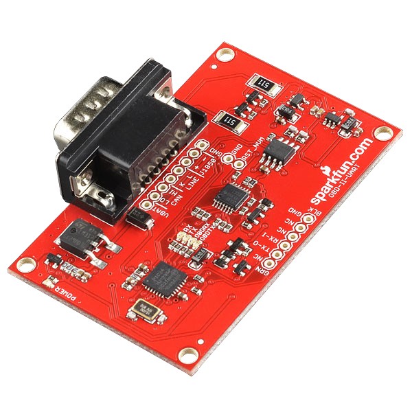
The SparkFun OBD-II UART board, a key component for interfacing with your car’s diagnostics.
This guide will be your roadmap to understanding and utilizing the OBD2 to serial interface. We will explore:
- The components of an OBD2 to serial interface and the hardware involved in the OBD-II UART board.
- The fundamental OBD-II commands that unlock your vehicle’s data.
- Step-by-step instructions for establishing a connection via FTDI to your computer, enabling direct data access.
- A practical guide to integrating the OBD2 to serial interface with an Arduino, showcasing data display on an LCD screen for embedded applications.
Whether you’re a seasoned automotive technician, a curious hobbyist, or an engineering student, this guide will provide the knowledge and practical steps to harness the power of the OBD2 to serial interface.
Essential Tools and Skills
To effectively follow this guide, you’ll need to gather a few essential tools and possess some basic technical understanding.
Required Tools:
- Soldering Iron: For securely attaching headers to the OBD-II UART board.
- Solder: To create robust electrical connections.
- Laptop: For serial communication and potentially Arduino programming.
Helpful Pre-requisite Knowledge:
A foundational understanding of basic electronics and serial communication is beneficial. If you’re new to these concepts, we recommend exploring these resources before proceeding:
[
Introductory Guide to Soldering Through-Hole Components
](https://learn.sparkfun.com/tutorials/how-to-solder-through-hole-soldering) Learn the essentials of through-hole soldering techniques.
[
Demystifying Serial Communication
](https://learn.sparkfun.com/tutorials/serial-communication) Understand the principles of asynchronous serial communication, including UARTs and baud rates.
[
Working with Wires: Stripping, Crimping, and More
](https://learn.sparkfun.com/tutorials/working-with-wire) Master the techniques for preparing and working with electrical wires.
[
What is Arduino? An Introduction to Microcontrollers
](https://learn.sparkfun.com/tutorials/what-is-an-arduino) Discover the world of Arduino and microcontroller basics.
[
Understanding Hexadecimal Numbering System
](https://learn.sparkfun.com/tutorials/hexadecimal) Learn to interpret and convert hexadecimal numbers, crucial for OBD-II data.
[
Getting Started with OBD-II: An Automotive Diagnostic Primer
](https://learn.sparkfun.com/tutorials/getting-started-with-obd-ii) Gain a comprehensive introduction to OBD-II protocols and automotive diagnostics.
Exploring the OBD-II UART Board: Hardware Overview
On-Board Diagnostics, Second Generation (OBD-II) is more than just a standard connector; it’s a comprehensive system designed to monitor and control vehicle emissions. Introduced in the US in 1994 and mandated for all 1996 and newer US vehicles, OBD-II (and its regional variations adopted in countries like Canada, Japan, and Australia) provides a standardized way to access a wealth of vehicle data.
OBD-II compliance means every vehicle is equipped with a standard Diagnostic Link Connector (DLC) and follows a defined protocol for communicating with the car’s computer, the Electronic Control Unit (ECU). Tapping into the OBD bus unlocks access to critical information such as:
- Malfunction Indicator Light (MIL) status (the “check engine light”)
- Diagnostic Trouble Codes (DTCs) – the error codes themselves
- Inspection and Maintenance (I/M) readiness data
- Freeze frames – snapshots of data when a fault occurs
- Vehicle Identification Number (VIN)
- Real-time parameters – engine speed, temperature, sensor readings, and much more.
For a deeper dive into the OBD-II protocol, Wikipedia offers a comprehensive resource: On-board diagnostics.
The heart of the OBD-II UART board is the STN1110, an OBD to UART interpreter chip. This sophisticated chip acts as a translator, converting the complex OBD-II protocols into simple serial UART messages. Critically, the STN1110 is fully compatible with the widely adopted ELM327 command set, making it versatile and easy to integrate into existing systems. The STN1110, built around a 16-bit processor, offers enhanced performance and features compared to other ELM327-compatible ICs. ScanTool provides extensive resources about the STN1110 on their website, which are valuable for advanced users.
Understanding the Board’s Design: Schematic and Pinout
The OBD-II UART board is ingeniously designed to support both CAN and OBD-II protocols, featuring both the STN1110 and the MCP2551 chips.
Schematic of the OBD-II UART board showing chip placements and connections
The schematic diagram of the OBD-II UART board, illustrating the circuit design and component interconnections.
Key components and features:
- STN1110: The central controller, managing communication across CAN, ISO, and J1850 OBD-II protocols.
- MCP2551: A CAN transceiver, enabling CAN bus communication.
- Voltage Regulation: Onboard regulation to both 5V and 3.3V ensures proper operation of all components.
- Power Source: The board is powered directly through the DB9 connector, drawing power from the vehicle’s OBD-II port.
Pinout Options:
The board provides two distinct connection interfaces:
-
6-Pin FTDI-Compatible Header: Located at the board’s edge, this header is designed for direct UART communication using an FTDI board. Crucially, only the TX, RX, and GND pins are connected on this header, simplifying UART interfacing.
-
8-Pin Header (near DB9 connector): This header expands connectivity, providing access to:
- VBAT line (vehicle battery voltage)
- CAN bus
- LINE bus
- J1850 bus
- Common Ground
This dual-header design offers flexibility for various applications, from simple serial data retrieval to more complex bus-level interactions. Now that we have a solid understanding of the hardware, let’s move on to establishing initial communication.
Establishing First Communication: Connecting to Your Vehicle and Computer
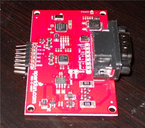
Soldering Headers for Reliable Connections
To create robust and reliable electrical connections with external components like an FTDI Basic or Arduino, soldering headers to the OBD-II UART board is essential. For basic serial communication with an FTDI Basic, male headers soldered to the 6-pin header row at the edge of the board provide the most straightforward setup. After soldering, your board should resemble the image below.
The OBD-II UART board with right-angle male headers soldered, ready for connection to an FTDI Basic.
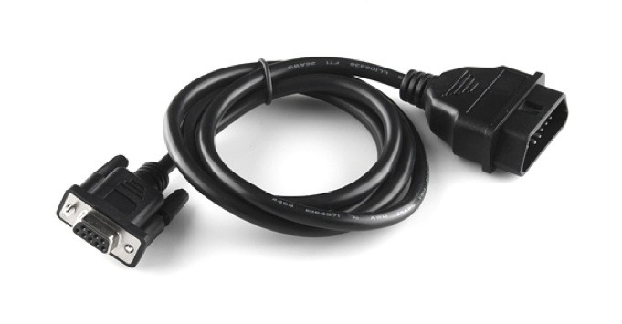
Connecting to Your Vehicle’s OBD Port
Locating your vehicle’s OBD port is the next step. The port’s location can vary depending on the car’s make and model; consult your owner’s manual if you have difficulty finding it. Typically, it’s found under the dashboard on the driver’s side.
Once located, connect the OBD-to-DB9 cable to your vehicle’s OBD port.
An OBD-II to DB9 cable, essential for connecting the OBD-II UART to your vehicle’s diagnostic port.
The OBD-II connector on these cables can sometimes be a tight fit, requiring a firm push to ensure a secure connection. It’s often easiest to first connect the cable to the vehicle’s OBD port, then connect the DB9 end to the OBD-II UART board.
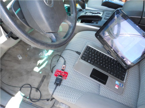
Serial Port Connection via FTDI
With headers soldered and the OBD-DB9 cable connected to your vehicle and the OBD-II UART board, you can establish serial communication using an FTDI Basic breakout board. The FTDI pinout is designed to directly match the 6-pin header on the OBD-II UART board, specifically utilizing the TX, RX, and GND connections.
Connect the FTDI board to your computer using a mini-USB cable. Then, open a serial terminal program on your computer (such as PuTTY, Tera Term, or the Arduino Serial Monitor). Configure the serial connection with the following settings:
- Baud Rate: 9600 bps
- Data bits: 8
- Stop bits: 1
- Parity: None
A connection setup illustrating the OBD-II UART connected to a vehicle and a computer via an FTDI Basic, ready for serial communication.
Communicating with AT Commands
Once your serial terminal is configured, you can communicate with the OBD-II board using AT commands. These commands, a standard for ELM327-compatible devices, always begin with “AT”. The OBD-II UART board is case-insensitive, so commands can be entered in uppercase or lowercase.
For a comprehensive list of available AT commands, consult the ELM327 AT Commands datasheet.
Testing the Connection:
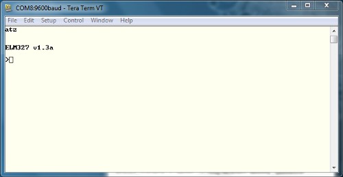
- Reset Command: Type
ATZin the terminal and press Enter. This command resets the OBD-II board. You should observe LEDs flashing on the board and a startup prompt appearing in the terminal window.
A serial terminal capture showing the “ATZ” command and the expected startup prompt response, confirming basic communication.
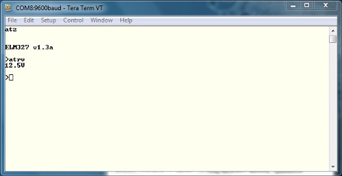
If you see garbled characters, double-check your serial port settings in the terminal program, ensuring they match the specified settings (9600 bps, 8N1).- Voltage Check: To verify basic functionality, try reading the OBD-II UART system voltage. Type
ATRVand press Enter. The board should respond with the system voltage.
A serial terminal output showing the “ATRV” command and the voltage reading, verifying the board’s voltage sensing capability.
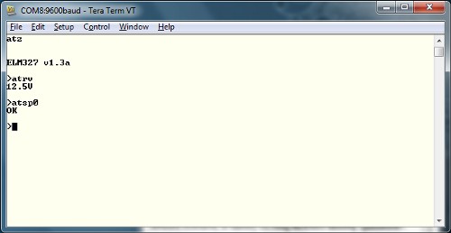
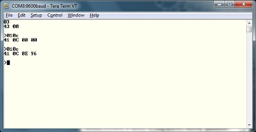
This voltage reading should be consistent with your vehicle's battery voltage, providing a basic health check of the connection.- Automatic Protocol Detection: To read vehicle-specific parameters, the OBD-II UART needs to be configured to the correct OBD protocol. While there are multiple OBD protocols, the OBD-II UART simplifies this by automatically detecting the correct protocol. Ensure your vehicle’s ignition is in the ‘On’ position (engine doesn’t need to be running). Send the command
ATSP0(that’s “ATSP” followed by a zero). The board will respond with “OK” once the protocol is successfully detected.
Serial terminal output showing “ATSP0” command and the “OK” response, confirming successful automatic protocol detection.
With successful protocol detection, your OBD2 to serial interface is ready to retrieve valuable vehicle data using OBD commands.
Decoding Vehicle Data: Understanding OBD Commands
OBD Command Structure
OBD commands are the key to requesting specific data from your vehicle’s ECU. These commands are constructed using hexadecimal codes represented as ASCII characters. Typically, OBD commands consist of two or more pairs of hexadecimal numbers, although some commands use only a single pair.
The first hexadecimal pair in an OBD command specifies the OBD mode. Subsequent hex pairs define the Parameter ID (PID) you wish to retrieve within that mode. There are 10 defined OBD modes, but not all vehicles support every mode. Consult your vehicle’s specific documentation to determine supported modes and PIDs.
Common OBD-II Modes:
| Mode Number (Hex) | Mode Description | Typical Use |
|---|---|---|
| 01 | Show current data | Real-time sensor readings, engine parameters |
| 02 | Show freeze frame data | Data captured when a DTC was set |
| 03 | Show diagnostic trouble codes | Retrieve stored DTCs (error codes) |
| 04 | Clear trouble codes | Reset DTCs and MIL (check engine light) |
| 05 | Oxygen sensor test results | O2 sensor performance data |
| 06 | On-board monitoring test results | Results of non-continuous system tests |
| 07 | Show pending trouble codes | DTCs that haven’t yet triggered the MIL |
| 08 | Control operation of component | Request control of specific systems |
| 09 | Request vehicle information | VIN, calibration IDs, etc. |
| 0A | Show permanent trouble codes | DTCs that cannot be cleared by mode 04 |
For a detailed understanding of OBD PIDs, Wikipedia provides a comprehensive resource: OBD-II PIDs. Vehicle manufacturers may also implement proprietary parameters beyond the standard PIDs. The ELM327 AT Commands datasheet is another valuable resource for exploring available commands and PIDs.
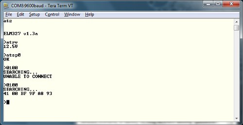
Requesting PID Support (Mode 01, PID 00):
A fundamental PID to start with is PID 00 within Mode 01. This PID, supported by virtually all OBD-compliant vehicles, provides a list of other PIDs supported by the car. In your serial terminal, type 0100 and press Enter. This translates to “In Mode 01, what PIDs are supported?”.
Serial terminal capture showing the “0100” command and the response indicating supported PIDs.
Understanding the OBD Response Structure:
OBD responses follow a consistent structure. The first byte (e.g., 0x41) indicates the requested mode (in this case, 0x40 + 0x01). The second byte is the requested PID (0x00). Subsequent bytes contain the data in response to the command. In the example above, 0xBF, 0x9F, 0xA8, and 0x93 represent the supported PIDs.
Reading Engine RPM (Mode 01, PID 0C):
Another commonly supported parameter is Engine RPM. Send the command 010C and press Enter. The response will be in hexadecimal format.
Serial terminal output showing the “010C” command and the hexadecimal response for Engine RPM.
The response structure remains the same: 0x41 (Mode 01 response), 0x0C (RPM parameter). The data bytes 0x0E 0x96 represent the RPM value. Converting 0x0E96 from hexadecimal to decimal yields 3734. However, RPM values are often reported in ¼ RPM increments, so dividing 3734 by 4 gives an idling RPM of approximately 933 RPM.
Explore the ELM327 datasheet for a wider range of PIDs to experiment with and unlock more data from your vehicle using the OBD2 to serial interface. Now, let’s explore connecting the OBD-II UART to an Arduino for embedded projects.
Integrating OBD2 to Serial with Arduino for Embedded Applications
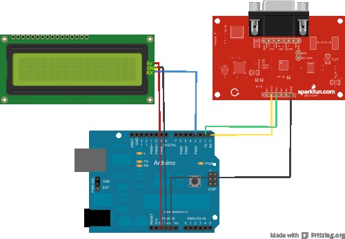
Connecting OBD-II UART to Arduino and LCD
Beyond direct computer connection, the OBD2 to serial interface becomes even more powerful when integrated with microcontrollers like Arduino. This allows for creating standalone, embedded automotive diagnostic and monitoring systems. In this section, we’ll guide you through connecting the OBD-II UART to an Arduino Uno and displaying real-time data on a serial LCD.
Hardware Requirements:
- Arduino Uno (or compatible 5V Arduino board)
- Jumper wires
- Serial LCD display
- OBD-II UART board (with soldered headers)
- OBD-II to DB9 cable
- Vehicle with OBD-II port
Wiring Diagram and Connection Table:
The setup requires only six connections between the Arduino, Serial LCD, and OBD-II UART.
Wiring diagram showing the connections between the OBD-II UART, Arduino Uno, and a Serial LCD for data display.
| Arduino Pin | Serial LCD Pin | OBD-II-UART Pin | Function |
|---|---|---|---|
| GND | GND | GND | Ground |
| 5V | 5V | None | 5V Power to LCD |
| D3 | Rx | None | LCD Receive |
| D0 (Rx) | None | Tx-O | Arduino Receive from OBD-II UART |
| D1 (Tx) | None | Rx-I | Arduino Transmit to OBD-II UART |
Arduino Sketch and Code Explanation:
Download the Arduino sketch from GitHub: OBDII_UART/Arduino Example. This sketch provides a basic framework for reading and displaying vehicle speed and RPM.
Important Note: When uploading the sketch to your Arduino, disconnect the OBD-II UART RX line (connected to Arduino TX-0). Leaving it connected can interfere with the code upload process and potentially cause issues.
Power Considerations: The Arduino in this setup is not powered by the OBD-II UART. You’ll need to power the Arduino separately, either via USB from your laptop or using an external power supply like a 9V battery with a 9V barrel jack adapter.
Sketch Code Breakdown:
The Arduino sketch is designed for simplicity, focusing on serial communication with the OBD-II UART and displaying received data on the LCD.
#include <SoftwareSerial.h>

// Create a software serial instance for the LCD
SoftwareSerial lcd(2, 3); // Arduino pin 3 to LCD Rx

char rxData[20];        // Buffer to store serial data
char rxIndex = 0;

int vehicleSpeed = 0;
int vehicleRPM = 0;

void setup() {
  lcd.begin(9600);          // Initialize LCD serial
  Serial.begin(9600);       // Initialize OBD-II UART serial

  lcd.write(254);         // Clear LCD
  lcd.write(1);

  lcd.print("Speed: ");
  lcd.write(254);
  lcd.write(128 + 64);    // Move cursor to second row
  lcd.print("RPM: ");

  delay(1500);
  Serial.println("ATZ");    // Reset OBD-II UART
  delay(2000);
  Serial.flush();         // Clear serial buffer
}

void loop() {
  Serial.flush();

  lcd.write(254);
  lcd.write(128 + 8);     // Cursor to speed position
  lcd.print("       ");    // Clear old speed data
  lcd.write(254);
  lcd.write(128 + 8);

  Serial.println("010D");    // Request vehicle speed
  getResponse();
  getResponse();          // Get two responses (echo and data)
  vehicleSpeed = strtol(&rxData[6], 0, 16);
  lcd.print(vehicleSpeed);
  lcd.print(" km/h");
  delay(100);

  Serial.flush();

  lcd.write(254);
  lcd.write(128 + 69);    // Cursor to RPM position
  lcd.print("       ");    // Clear old RPM data
  lcd.write(254);
  lcd.write(128 + 69);

  Serial.println("010C");    // Request engine RPM
  getResponse();
  getResponse();
  vehicleRPM = ((strtol(&rxData[6], 0, 16) * 256) + strtol(&rxData[9], 0, 16)) / 4;
  lcd.print(vehicleRPM);
  delay(100);
}

// Function to receive serial data until carriage return
void getResponse(void) {
  char inChar = 0;
  while (inChar != 'r') {
    if (Serial.available() > 0) {
      if (Serial.peek() == 'r') {
        inChar = Serial.read();
        rxData[rxIndex] = '';
        rxIndex = 0;
      } else {
        inChar = Serial.read();
        rxData[rxIndex++] = inChar;
      }
    }
  }
}
Code Functionality:
- Includes
SoftwareSerial.h: Enables serial communication with the LCD on Arduino pins D2 and D3, freeing up the primary serial port for OBD-II UART communication. setup()function:- Initializes serial communication for both the LCD and OBD-II UART at 9600 bps.
- Clears the LCD screen and prints “Speed:” and “RPM:” labels.
- Resets the OBD-II UART (
ATZcommand).
loop()function:- Clears previous speed and RPM values on the LCD.
- Sends OBD command
010Dto request vehicle speed. - Calls
getResponse()twice to receive both the echoed command and the data response from the OBD-II UART. - Converts the received hexadecimal speed data to an integer using
strtol()and displays it on the LCD. - Repeats the process for engine RPM using OBD command
010C.
getResponse()function:- Reads incoming serial data from the OBD-II UART and stores it in the
rxDatabuffer until a carriage return character (r) is received, indicating the end of the response.
- Reads incoming serial data from the OBD-II UART and stores it in the
By uploading this sketch to your Arduino, connecting the hardware as described, and connecting to your vehicle, you’ll be able to display real-time vehicle speed and RPM on the serial LCD, demonstrating a practical embedded application of the OBD2 to serial interface.
Expanding Your OBD-II Projects: Resources and Further Exploration
Now that you’ve mastered the basics of OBD2 to serial communication and explored examples with both computers and Arduino, the possibilities for automotive projects are vast.
Software Resources
For visualizing and analyzing OBD-II data on your computer without coding, several free software options are available. These programs often provide graphical interfaces for displaying data in real-time graphs, gauges, and logs.
- GitHub Repo: OBDII_UART/Software: Explore the “Software” folder in the GitHub repository for potential software tools and resources.
- General OBD-II Freeware: Search online for “free OBD-II software” to discover various PC-based applications compatible with ELM327 interfaces.
Project Inspiration and Further Learning
Ready to take your OBD-II projects to the next level? Consider these related tutorials and project ideas:
- Advanced Parameter Monitoring: Expand the Arduino sketch to read and display a wider range of vehicle parameters beyond speed and RPM, such as coolant temperature, intake air temperature, throttle position, and more. Use the PID support command (
0100) to discover supported PIDs for your vehicle. - Data Logging and Analysis: Modify your setup to log OBD-II data to an SD card or transmit it wirelessly to a remote server for later analysis. This can be invaluable for diagnosing intermittent issues or tracking vehicle performance over time.
- Custom Dashboards and Displays: Design custom dashboards using graphical LCDs or smartphone apps to display OBD-II data in visually appealing and informative ways.
- Performance Tuning and Optimization: For advanced users, OBD-II data can be used to monitor engine performance and potentially optimize tuning parameters (with caution and expert knowledge).
- Vehicle Telematics and IoT Applications: Integrate OBD-II data with IoT platforms to create connected car applications, such as remote vehicle monitoring, geofencing, and driver behavior analysis.
[
CAN-BUS Shield Hookup Guide: Expanding Automotive Communication
](https://learn.sparkfun.com/tutorials/can-bus-shield-hookup-guide) Explore the Controller Area Network (CAN bus), another critical automotive communication protocol, and learn how to interface with it using a CAN-BUS shield.
[
Getting Started with OBD-II: Deeper Dive into Protocols
](https://learn.sparkfun.com/tutorials/getting-started-with-obd-ii) Further your understanding of the intricacies of OBD-II protocols and standards for advanced diagnostics and communication.
[
AST-CAN485 Hookup Guide: Industrial Automotive Control
](https://learn.sparkfun.com/tutorials/ast-can485-hookup-guide) Discover the AST CAN485, a compact Arduino platform with integrated CAN and RS485, ideal for industrial automotive applications and interfacing with diverse vehicle systems.
By leveraging the OBD2 to serial interface and the resources outlined in this guide, you can unlock a wealth of automotive data and create innovative projects that enhance your understanding of vehicle systems and push the boundaries of DIY automotive technology.