Developing and testing OBD2 applications for your car can be a cumbersome process. Constantly moving your Arduino prototype between your workbench and your vehicle, just to find a minor code adjustment is needed, can quickly become frustrating. If you’ve been searching for a more convenient and efficient method, you’re in the right place. This guide explores how to build your own Obd2 Simulator Arduino project, allowing you to test your automotive diagnostics code from the comfort of your home or workshop.
Like many DIY automotive enthusiasts, I encountered the same problem while developing an Arduino OBD2 scanner. The iterative process of coding, uploading, and testing in the car was time-consuming and inconvenient. The need for a bench testing solution became apparent, leading me to investigate obd2 simulator arduino options.
My search for readily available DIY obd2 simulator arduino projects yielded surprisingly few results. While some commercial solutions exist, such as the FreeMatics simulator, the high price point and closed-source nature were significant drawbacks for a hobbyist. The open-source spirit of Arduino encourages DIY solutions, and the idea of spending a significant amount on a tool that could be built seemed counterintuitive.
A breadboard view of an Arduino UNO setup with various electronic components connected, highlighting a DIY electronics project in progress.
Driven by the desire for a cost-effective and open-source alternative, I embarked on creating my own obd2 simulator arduino. This project became a necessary detour in my original OBD2 scanner development, but ultimately provided a valuable tool for streamlined testing. The challenge lay in accurately simulating OBD2 communication and sending Parameter IDs (PIDs) in the correct format. After some dedicated effort, I successfully established communication with standard OBD2 diagnostic software, proving the viability of the obd2 simulator arduino concept.
To replicate this project and build your own obd2 simulator arduino, you will need the following components:
- Arduino UNO: The microcontroller brain of the simulator.
- CAN-BUS Shield: Enables your Arduino to communicate over the Controller Area Network (CAN) bus, which is fundamental to OBD2 communication in most modern vehicles.
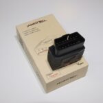
- ELM327 Interface (USB, Bluetooth, or WiFi): Acts as the interface between your computer and the simulated OBD2 system. The connection type (USB, Bluetooth, or WiFi) is not critical, as long as it establishes a communication port on your computer.
- OBD2 Diagnostic Software: Any standard OBD2 diagnostic software compatible with your ELM327 interface can be used to test the simulator. Software typically included with your ELM327 scanner is perfectly suitable for this purpose.
A close-up shot displaying the electronic components required for building an OBD2 simulator, including an Arduino board, a CAN-BUS shield, and an ELM327 interface.
By assembling these components and developing the appropriate Arduino code (which is the core of a functional obd2 simulator arduino and would be the next step in a more detailed guide), you can create a powerful tool for testing and refining your OBD2 applications without needing constant access to a vehicle. This DIY obd2 simulator arduino approach not only saves time and effort but also provides a deeper understanding of OBD2 communication protocols and Arduino programming in automotive contexts.