The On-Board Diagnostic system, more commonly known as OBD2, is a cornerstone of modern automotive technology. As a mechanic, understanding the Obd2 Purpose is not just beneficial—it’s essential. This guide breaks down the intricacies of OBD2, explaining its function, history, and why it’s indispensable for anyone working with vehicles today.
What is OBD2 and Its Core Purpose?
OBD2 is essentially your vehicle’s internal health monitor. Think of it as a built-in doctor constantly checking vital signs. Its primary obd2 purpose is to monitor vehicle systems, primarily for emission control, but its capabilities extend far beyond. When something goes wrong, like an engine misfire or a sensor malfunction, OBD2 detects it, stores a diagnostic trouble code (DTC), and often illuminates the malfunction indicator light (MIL), commonly known as the “check engine light,” on your dashboard.
For mechanics, the obd2 purpose becomes incredibly practical. By connecting an OBD2 scanner to the 16-pin OBD2 connector, typically located under the dashboard near the steering wheel, you can communicate with the vehicle’s computer. This connection allows you to retrieve those stored DTCs, as well as access real-time data like speed, engine RPM, and sensor readings. This data is crucial for diagnosing issues efficiently and effectively, saving time and labor in the repair process.
Does Your Car Have OBD2?
For most modern vehicles, the answer is almost certainly yes. The standardization of OBD2 means that nearly every non-electric car manufactured since the mid-1990s is equipped with it. You can easily identify an OBD2 system by the presence of a standardized 16-pin connector.
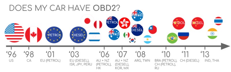
However, it’s worth noting that while most cars have a 16-pin connector, older models might have one that doesn’t fully support the OBD2 protocol. Compliance is generally determined by the vehicle’s market and manufacturing date. As a rule of thumb, if your car was bought new in the regions and years specified below, it most likely supports OBD2:
The History and Evolution of OBD2 Purpose
The story of OBD2 begins in California. Driven by the California Air Resources Board (CARB), the initial obd2 purpose was strictly focused on emission control. Starting in 1991, CARB mandated on-board diagnostics in all new vehicles sold in California to monitor and reduce vehicle emissions.
The Society of Automotive Engineers (SAE) played a pivotal role in standardizing this technology. They recommended the OBD2 standard, leading to uniform diagnostic trouble codes (DTCs) and a standardized OBD connector across different vehicle manufacturers through the SAE J1962 standard.
This standardization paved the way for the widespread adoption of OBD2, with its implementation progressing through key milestones:
- 1996: OBD2 became mandatory in the USA for cars and light trucks.
- 2001: The European Union mandated OBD2 for gasoline cars.
- 2003: The EU extended the mandate to include diesel cars (EOBD).
- 2005: OBD2 was required in the US for medium-duty vehicles.
- 2008: US vehicles were required to use ISO 15765-4 (CAN) as the communication basis for OBD2.
- 2010: OBD2 became mandatory for heavy-duty vehicles in the US.
The Future of OBD2: Evolving Purposes
While the original obd2 purpose was emission control, its role is expanding, though facing potential shifts in the automotive landscape.
One significant trend is the rise of electric vehicles (EVs). Ironically, because the legislated obd2 purpose centered on emissions, EVs, having none, aren’t strictly required to support OBD2. In practice, most modern EVs don’t use standard OBD2 protocols but rely on OEM-specific UDS communication. This poses a challenge for aftermarket diagnostics, although reverse engineering efforts are making inroads for brands like Tesla, Hyundai/Kia, Nissan, and VW/Skoda.
Another evolution is the development of enhanced OBD protocols like WWH-OBD (World Wide Harmonized OBD) and OBDonUDS (OBD on UDS). These are designed to improve data richness and streamline communication by using the UDS protocol as a foundation, addressing some limitations of the original OBD2.
Looking further ahead, the concept of OBD3 emerges, aiming to integrate telematics into vehicles. The idea is to add a radio transponder to vehicles, enabling automatic transmission of Vehicle Identification Numbers (VIN) and DTCs to a central server for remote emission checks and diagnostics. While offering convenience and efficiency, this raises privacy concerns and political challenges related to data surveillance. Devices like the CANedge2 and CANedge3 already demonstrate the feasibility of transmitting CAN/OBD2 data via WiFi or cellular networks.
However, the future of open OBD2 access isn’t entirely clear. The German car industry has voiced intentions to limit third-party access to OBD2 data while driving, proposing to centralize data collection within manufacturer servers. This shift, argued in the name of security and preventing car hacking, is seen by many as a move to control automotive data and potentially disrupt the market for third-party OBD2 services.
Get our ‘Ultimate CAN Guide’
Want to become a CAN bus expert?
Get our 12 ‘simple intros’ in one 160+ page PDF:
Download now
Understanding OBD2 Standards and Protocols
OBD2 operates as a higher-layer protocol, like a language spoken over a communication network. In most modern cars, this network is the Controller Area Network (CAN) bus. Understanding this layered approach is crucial for grasping the full obd2 purpose. Think of CAN bus as the phone line and OBD2 as the conversation happening over it. This is similar to other CAN-based protocols like J1939, CANopen, and NMEA 2000.
OBD2 standards define various aspects, including the physical OBD2 connector, the lower-layer communication protocols, and OBD2 parameter IDs (PIDs). These standards are detailed in documents from both SAE (primarily US standards) and ISO (international standards), often with technical equivalencies, such as SAE J1979 vs. ISO 15031-5 and SAE J1962 vs. ISO 15031-3.
The standards can be visualized using the 7-layer OSI model, illustrating how OBD2 builds upon lower-level communication layers.
The OBD2 Connector: Your Access Point [SAE J1962]
The 16-pin OBD2 connector, specified by SAE J1962 and ISO 15031-3, is your physical gateway to accessing vehicle data. This standardized connector simplifies diagnostics and data retrieval.
Key features of the OBD2 connector include:
- Location: Typically found near the steering wheel, though its exact location may be hidden behind a panel.
- Pin 16: Provides battery power, often active even when the ignition is off.
- Pinout Variation: The specific pinout depends on the communication protocol used by the vehicle.
- CAN Bus Connection: In CAN bus based OBD2 systems, pins 6 (CAN-H) and 14 (CAN-L) are crucial for communication.
OBD2 Connector Types: A vs. B
You might encounter two main types of OBD2 connectors: Type A and Type B. Type A is standard in cars and light vehicles, while Type B is more common in medium and heavy-duty vehicles.
While both types share similar pinouts, they differ in power supply output (12V for Type A, 24V for Type B) and often in baud rates (500K for cars, 250K or 500K for heavy-duty vehicles).
Visually, a Type B OBD2 connector has a distinguishing interrupted groove in the middle. This makes Type B OBD2 adapter cables compatible with both Type A and Type B sockets, whereas a Type A adapter will only fit Type A sockets.
OBD2 Communication via CAN Bus (ISO 15765-4)
Since 2008, CAN bus (ISO 11898) has been the mandated lower-layer protocol for OBD2 in US vehicles, as defined by ISO 15765-4, also known as Diagnostics over CAN (DoCAN). This standard outlines specific requirements for using CAN bus in OBD2 systems, focusing on the physical, data link, and network layers.
ISO 15765-4 standardizes:
- Bit-rate: Must be either 250K or 500K.
- CAN IDs: Supports both 11-bit and 29-bit CAN identifiers.
- Specific CAN IDs: Defines specific CAN IDs for OBD requests and responses.
- Data Length: Diagnostic CAN frames must have a data length of 8 bytes.
- Cable Length: OBD2 adapter cables are limited to a maximum length of 5 meters.
OBD2 CAN Identifiers (11-bit, 29-bit)
OBD2 communication relies on request and response message exchanges. In most cars using 11-bit CAN IDs, functional addressing uses CAN ID 0x7DF to query all OBD2-compliant ECUs for data on a requested parameter. Physical addressing, using CAN IDs 0x7E0-0x7E7, allows targeting specific ECUs but is less common for OBD2.
ECU responses typically use 11-bit IDs in the range 0x7E8-0x7EF, with 0x7E8 (Engine Control Module – ECM) and 0x7E9 (Transmission Control Module – TCM) being the most frequent response IDs.
Some vehicles, particularly vans and medium/heavy-duty vehicles, may employ extended 29-bit CAN identifiers for OBD2 communication. In these cases, the functional addressing CAN ID is 0x18DB33F1, with responses using IDs ranging from 0x18DAF100 to 0x18DAF1FF, often represented in J1939 PGN format as PGN 0xDA00 (55808), reserved for ISO 15765-2 in the J1939-71 standard.
OBD2 vs. Proprietary CAN Protocols
It’s crucial to understand that OBD2 is an additional protocol layer, not the primary communication system within a vehicle. Vehicle ECUs rely on OEM-specific, proprietary CAN protocols for their core functions. These protocols are unique to each manufacturer, model, and year, and interpreting this data typically requires reverse engineering.
Connecting a CAN bus data logger to the OBD2 port might capture OEM-specific CAN data, often broadcast at high rates (1000-2000 frames/second). However, newer vehicles often incorporate a gateway that restricts OBD2 port access to OBD2 communication only, blocking access to the underlying OEM-specific CAN data.
Think of OBD2 as a separate diagnostic “channel” running alongside the vehicle’s main communication network.
Bit-rate and ID Validation
OBD2 over CAN can use two bit-rates (250K, 500K) and two CAN ID lengths (11-bit, 29-bit), resulting in four possible combinations. Modern cars commonly use 500K and 11-bit IDs, but diagnostic tools should systematically validate these parameters.
ISO 15765-4 outlines an initialization sequence to determine the correct combination. This process leverages the requirement that OBD2-compliant vehicles must respond to a specific mandatory OBD2 request (related to OBD2 PIDs) and detects CAN error frames caused by incorrect bit-rate transmissions.
Newer ISO 15765-4 versions also account for vehicles supporting OBD communication via OBDonUDS instead of OBDonEDS. While this article primarily focuses on OBDonEDS (emission diagnostic service, as per ISO 15031-5/SAE J1979), WWH-OBD/OBDonUDS (Unified Diagnostic Service, as per ISO 14229, ISO 27145-3/SAE J1979-2) is increasingly relevant, especially in EU trucks and buses.
To differentiate between OBDonEDS and OBDonUDS, diagnostic tools can send UDS requests with 11-bit/29-bit functional address IDs for service 0x22 and data identifier (DID) 0xF810 (protocol identification). Vehicles supporting OBDonUDS should respond to this DID.
Currently, OBDonEDS (also known as OBD2, SAE OBD, EOBD, or ISO OBD) is prevalent in most non-electric vehicles, while WWH-OBD is mainly found in EU commercial vehicles.
Five Lower-Layer OBD2 Protocols
While CAN (ISO 15765) is now dominant, older vehicles (pre-2008) may use one of four other lower-layer protocols for OBD2. Knowing these is helpful when working with older cars. The OBD2 connector pinout can sometimes indicate the protocol in use.
- ISO 15765 (CAN bus): Mandatory in US cars since 2008 and widely used today.
- ISO14230-4 (KWP2000): Keyword Protocol 2000, common in 2003+ Asian cars.
- ISO 9141-2: Used in EU, Chrysler, and Asian cars in 2000-2004.
- SAE J1850 (VPW): Variable Pulse Width Modulation, primarily in older GM vehicles.
- SAE J1850 (PWM): Pulse Width Modulation, mainly in older Ford vehicles.
Transporting OBD2 Messages via ISO-TP [ISO 15765-2]
OBD2 data transmitted over CAN bus uses the ISO-TP (ISO 15765-2) transport protocol. This is essential because it allows for transmitting data payloads larger than the 8-byte limit of a single CAN frame. This capability is needed in OBD2 for tasks like retrieving the Vehicle Identification Number (VIN) or Diagnostic Trouble Codes (DTCs). ISO 15765-2 handles segmentation, flow control, and reassembly of these larger messages.
However, many OBD2 data requests and responses fit within a single CAN frame. In these cases, ISO 15765-2 specifies the use of a ‘Single Frame’ (SF) format. The first byte of the data field (PCI field) indicates the payload length (excluding padding), leaving 7 bytes for OBD2-specific data.
The OBD2 Diagnostic Message [SAE J1979, ISO 15031-5]
To effectively work with OBD2 data, understanding the structure of an OBD2 diagnostic message is crucial. In its simplest form, a ‘Single Frame’ OBD2 CAN message includes a CAN identifier, a data length indicator (PCI field), and the data payload. The payload itself is structured into a Mode byte, a Parameter ID (PID), and data bytes.
Example: OBD2 Request/Response
Consider a practical example: requesting ‘Vehicle Speed’. A diagnostic tool sends a request message with CAN ID 0x7DF and a 2-byte payload: Mode 0x01 and PID 0x0D. The vehicle responds with a CAN ID 0x7E8 message and a 3-byte payload. The vehicle speed value is encoded in the 4th byte of the CAN data field, in this case, 0x32 (decimal 50).
By consulting the OBD2 PID documentation for PID 0x0D, you can determine that 0x32 corresponds to a vehicle speed of 50 km/h. This process of understanding OBD2 modes and PIDs is fundamental to interpreting OBD2 data.
The 10 OBD2 Services (aka Modes)
OBD2 defines ten diagnostic services, also called modes, each serving a specific obd2 purpose. Mode 0x01 is used to request current, real-time data parameters, while other modes are designed for retrieving and clearing diagnostic trouble codes (DTCs) or accessing freeze frame data (snapshots of data when a DTC was set).
It’s important to note that not all vehicles are required to support all ten OBD2 modes. Furthermore, manufacturers may implement OEM-specific modes beyond the ten standardized ones.
In OBD2 messages, the mode is indicated in the second byte of the data payload. In a request message, the mode is included directly (e.g., 0x01). In a response message, 0x40 is added to the requested mode value (e.g., a response to mode 0x01 will start with 0x41).
OBD2 Parameter IDs (PIDs)
Within each OBD2 mode, Parameter IDs (PIDs) specify the particular data being requested or reported. Mode 0x01, for example, includes approximately 200 standardized PIDs providing real-time data on parameters like speed, RPM, coolant temperature, and fuel level. However, vehicles typically support only a subset of these defined PIDs.
One PID stands out for its diagnostic significance: PID 0x00 in mode 0x01. If an emissions-related ECU supports any OBD2 services, it must support mode 0x01 PID 0x00. Responding to this PID, the ECU indicates which PIDs from 0x01 to 0x20 it supports. This makes PID 0x00 a fundamental tool for verifying OBD2 compatibility and discovering supported parameters. Similarly, PIDs 0x20, 0x40, 0x60, and so on, are used to determine support for subsequent PID ranges within mode 0x01.
Tip: OBD2 PID Overview Tool
SAE J1979 and ISO 15031-5 appendices detail the scaling and decoding information for standard OBD2 PIDs, essential for converting raw data into meaningful physical values.
For quick lookup of mode 0x01 PIDs, consider using an OBD2 PID overview tool. This can assist in constructing OBD2 request frames and dynamically decoding responses.
OBD2 PID overview tool
How to Log and Decode OBD2 Data
Let’s look at a practical example of logging OBD2 data using a CANedge CAN bus data logger. The CANedge allows configuration of custom CAN frames for transmission, making it suitable for OBD2 data logging. Connecting it to your vehicle’s OBD2 port is straightforward with an OBD2-DB9 adapter cable.
You can send a CAN frame at e.g. 500K, then check if it is successfully sent
The responses to ‘Supported PIDs’ can be reviewed in asammdf
#1: Test Bit-rate, IDs & Supported PIDs
Following ISO 15765-4 recommendations, you can use the CANedge to test and determine the correct bit-rate, CAN IDs, and supported PIDs for a specific vehicle:
- Bit-rate Test: Send a CAN frame at 500K and check for successful transmission. If unsuccessful, try 250K.
- Bit-rate Configuration: Use the identified bit-rate for subsequent communication.
- Supported PIDs Request: Send multiple ‘Supported PIDs’ requests (Mode 0x01, PID 0x00) and analyze the responses.
- CAN ID Determination: Based on response IDs (0x7E8-0x7EF or 0x18DAF1xx), determine if the vehicle uses 11-bit or 29-bit CAN IDs for OBD2.
- PID Support Identification: Analyze the response data to identify the specific PIDs supported by the vehicle.
Pre-configured settings are often available to simplify these initial tests. Most post-2008 non-EV cars typically support 40-80 PIDs using 500K bit-rate, 11-bit CAN IDs, and the OBD2/OBDonEDS protocol.
As seen in the asammdf GUI example, using the functional request ID 0x7DF can result in multiple responses to a single OBD request, as all compliant ECUs respond. The ECM ECU (0x7E8) often mirrors the PID support of other ECUs, suggesting that using physical addressing (e.g., 0x7E0) to target the ECM directly can reduce bus load in subsequent requests.
#2: Configure OBD2 PID Requests
Once you’ve identified the supported PIDs, bit-rate, and CAN IDs, configure your data logger to request the PIDs of interest. Consider these points:
- CAN IDs: Switch to ‘Physical Addressing’ request IDs (e.g., 0x7E0) for more targeted requests and fewer responses.
- Request Spacing: Introduce a delay of 300-500 ms between OBD2 requests to prevent overwhelming ECUs and ensure reliable responses.
- Battery Management: Implement triggers to stop transmissions when the vehicle is inactive to conserve battery power and prevent ECU “wake-up.”
- Data Filtering: Apply filters to record only OBD2 responses if OEM-specific CAN data is also present on the bus.
With these configurations, your data logger is ready to record raw OBD2 data efficiently.
An example list of CANedge OBD2 PID requests
asammdf lets you DBC decode and visualize OBD2 data
#3: DBC Decode Raw OBD2 Data
To analyze and visualize the logged raw OBD2 data, you need to decode it into physical values. Decoding information is available in ISO 15031-5/SAE J1979 and online resources like Wikipedia. A free OBD2 DBC file is available to simplify DBC decoding in most CAN bus software tools.
Decoding OBD2 data is more complex than standard CAN signal decoding. Because different OBD2 PIDs are transmitted using the same CAN ID (e.g., 0x7E8), the CAN ID alone is insufficient to identify the signal. Instead, decoding requires considering the CAN ID, OBD2 mode, and OBD2 PID – a form of multiplexing called ‘extended multiplexing‘. This can be implemented in DBC files.
CANedge: OBD2 Data Logger
The CANedge offers a user-friendly solution for recording OBD2 data directly to an SD card (8-32 GB). Simply connect it to a vehicle to start logging, and utilize free software/APIs and the provided OBD2 DBC file for data decoding and analysis.
OBD2 logger intro
CANedge
OBD2 Multi-Frame Examples [ISO-TP]
While many OBD2 interactions are single-frame, some require multi-frame communication via ISO-TP (ISO 15765-2). Multi-frame communication is necessary for larger data transfers, like retrieving VIN or DTCs, and involves flow control frames. In practice, a static flow control frame can be sent approximately 50 ms after the initial request frame, as demonstrated in CANedge configurations.
Analyzing multi-frame OBD2 responses requires CAN software/API tools with ISO-TP support, such as CANedge MF4 decoders.
Example 1: OBD2 Vehicle Identification Number (VIN)
Retrieving the VIN via OBD2 mode 0x09 PID 0x02 is a common multi-frame example.
The diagnostic tool sends a Single Frame request with PCI field (0x02), service identifier (0x09), and PID (0x02). The vehicle responds with a First Frame containing PCI, length (0x014 = 20 bytes), mode (0x49), and PID (0x02). Following the PID is the Number Of Data Items (NODI) byte (0x01 in this case), and then the 17 bytes representing the VIN, which can be converted from HEX to ASCII.
Example 2: OBD2 Multi-PID Request (6x)
OBD2 allows requesting up to six mode 0x01 PIDs in a single request frame. The ECU responds with data for supported PIDs, potentially using multi-frame responses. While efficient, this method complicates generic DBC file use due to signal encoding specific to the request. It is generally not recommended for practical data logging due to decoding complexities.
Decoding multi-PID responses via DBC files is challenging because the payload structure depends on the requested PIDs, making a generalized DBC difficult to create. While custom scripts interpreting request and response messages can be used, this approach is less scalable.
Example 3: OBD2 Diagnostic Trouble Codes (DTCs)
Mode 0x03 requests emissions-related Diagnostic Trouble Codes (DTCs). The request doesn’t include a PID. The ECU responds with the number of stored DTCs (or zero if none), with each DTC occupying 2 bytes. Multi-frame responses are used if more than two DTCs are stored.
The 2-byte DTC value is structured into a category (first 2 bits) and a 4-digit code (14 bits), typically displayed in hexadecimal. Decoded DTC values can be looked up using OBD2 DTC lookup tools.
OBD2 Data Logging – Use Case Examples
The versatility of OBD2 data logging opens up numerous applications across various sectors:
Logging data from cars
OBD2 data helps optimize fuel consumption, improve driving habits, test prototype components, and refine insurance risk assessments.
obd2 logger
Real-time car diagnostics
OBD2 interfaces enable real-time streaming of vehicle data, facilitating immediate diagnostics and troubleshooting.
obd2 streaming
Predictive maintenance
Cloud-connected OBD2 loggers allow continuous vehicle monitoring for predictive maintenance, minimizing breakdowns and downtime.
predictive maintenance
Vehicle blackbox logger
OBD2 loggers act as ‘black boxes’ in vehicles, recording crucial data for accident analysis, warranty validation, and diagnostic insights.
can bus blackbox
Do you have an OBD2 data logging use case? Reach out for free sparring!
Contact us
For more intros, see our guides section – or download the ‘Ultimate Guide’ PDF.
Need to log/stream OBD2 data?
Get your OBD2 data logger today!
Buy now Contact us
Recommended for you
OBD2 DATA LOGGER: EASILY LOG & CONVERT OBD2 DATA
CANEDGE2 – PRO CAN IoT LOGGER
[