The On-Board Diagnostics II (OBD2) system has become an indispensable part of modern vehicle maintenance and repair. For both professional mechanics and automotive enthusiasts, understanding the intricacies of the OBD2 system is crucial. Among the various components of OBD2, the Obd2 Power Pin, specifically pin 16, plays a fundamental role. This guide will delve into the significance of the OBD2 power pin, its function, and its importance in vehicle diagnostics.
What is OBD2 and Why is the Power Pin Important?
OBD2 is a standardized system in vehicles that monitors and reports on various aspects of a vehicle’s performance and health. It provides access to diagnostic trouble codes (DTCs) and real-time data, helping to identify issues and ensure vehicles are running efficiently and cleanly. The OBD2 system communicates through a 16-pin connector, typically located within easy reach of the driver’s seat.
The obd2 power pin, specifically pin 16, is critical because it provides the power supply for external OBD2 devices, such as scanners and data loggers. Without a functioning power pin, these tools cannot interface with the vehicle’s diagnostic system. This power pin ensures that diagnostic equipment can draw the necessary energy directly from the vehicle’s battery to perform tests, read codes, and access vehicle data, even when the ignition is off in some cases.
Understanding OBD2: On-Board Diagnostics and the Malfunction Indicator Light (MIL).
OBD2 Compliance and History: The Role of Standardization
The standardization of OBD2 was driven by environmental regulations, starting in California with the California Air Resources Board (CARB) in the early 1990s. The Society of Automotive Engineers (SAE) played a crucial role in defining the OBD2 standard, including the SAE J1962 standard for the OBD2 connector, ensuring uniformity across different vehicle manufacturers.
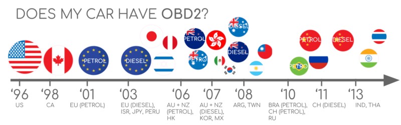
The implementation of OBD2 became progressively mandatory:
- 1996: OBD2 became mandatory in the USA for cars and light trucks.
- 2001: Required in the EU for gasoline cars.
- 2003: Required in the EU for diesel cars (EOBD).
- 2005: OBD2 was required in the US for medium-duty vehicles.
- 2008: US cars mandated to use ISO 15765-4 (CAN) as the OBD2 communication protocol.
- 2010: OBD2 became mandatory in US heavy-duty vehicles.
This history of standardization highlights the importance of a consistent interface, where the obd2 power pin is a fixed and reliable element across compliant vehicles, enabling universal diagnostic access.
Determining OBD2 Compliance: Check vehicle purchase location and year.
OBD2 History: From Emission Control to Comprehensive Vehicle Data Access.
OBD2 Timeline: Key Milestones in On-Board Diagnostics Development.
OBD2 Future Trends: Remote Diagnostics, Emissions Testing, and IoT Integration.
The Future of OBD2 and Access to Vehicle Data
While OBD2 remains crucial, the automotive landscape is evolving. Electric vehicles (EVs), for example, often do not fully adhere to standard OBD2 protocols for emissions monitoring, as they have no tailpipe emissions. Many EVs utilize OEM-specific protocols like UDS (Unified Diagnostic Services), making generic OBD2 tools less effective. However, the physical OBD2 connector, including the obd2 power pin, might still be present to provide a standardized physical interface, even if the communication protocol is different.
Emerging standards like WWH-OBD (World Wide Harmonized OBD) and OBDonUDS (OBD on UDS) aim to modernize OBD communication by leveraging the UDS protocol for enhanced data access and standardization. The concept of OBD3 envisions integrating telematics for remote diagnostics and emissions monitoring, potentially through wireless communication, but the physical OBD2 connector, and thus the obd2 power pin, remains relevant for direct tool connection and data retrieval.
The automotive industry is also debating the future accessibility of OBD2 data for third parties. Concerns about data security and the rise of ‘automotive big data’ have led to discussions about controlling access to vehicle data, potentially limiting the current open access provided through the OBD2 port. Despite these potential shifts, the fundamental need for a reliable power source for diagnostic tools, provided by the obd2 power pin, is unlikely to diminish.
OBD2 Future Challenges: Data Access in Electric Vehicles.
Understanding CAN Bus and OBD2 Standards
OBD2 functions as a high-layer protocol, similar to a language, while CAN (Controller Area Network) bus is the communication method, analogous to a phone line. OBD2 standards define the connector, communication protocols, and Parameter IDs (PIDs), among other things. These standards are often structured using the 7-layer OSI model, with both SAE and ISO standards contributing to different layers, reflecting US and EU standardization efforts.
Within this framework, the obd2 power pin ensures that regardless of the communication protocol (CAN, KWP2000, ISO 9141, SAE J1850), external diagnostic tools can consistently receive power through pin 16 of the standardized connector.
OBD2 and CAN Bus in the OSI Model: Layered Communication Standards.
OBD2 Connector Pinout: Standard Socket (Type A) and Pin Assignments.
The OBD2 Connector and the Power Pin [SAE J1962 / ISO 15031-3]
The OBD2 connector, standardized under SAE J1962 and ISO 15031-3, is a 16-pin Data Link Connector (DLC) designed for easy access to vehicle data. The connector is usually located under the dashboard, near the steering wheel, though its exact location can vary.
Pin 16 of the OBD2 connector is specifically designated as the battery power supply pin. This pin typically provides a 12V or 24V power source directly from the vehicle’s battery, even when the ignition is off. This constant power supply is crucial for OBD2 scanners and loggers to operate. The obd2 power pin ensures that diagnostic tools have a stable and independent power source, separate from the vehicle’s ignition system.
Key points regarding the OBD2 connector and the power pin:
- Pin 16: Battery Power: Provides battery voltage to OBD2 devices.
- Location: Generally near the steering wheel, but can be hidden.
- Pinout Variation: Pin assignments vary based on the communication protocol used by the vehicle.
- CAN Bus Integration: For CAN bus systems, pins 6 (CAN-High) and 14 (CAN-Low) are used for data communication.
Understanding the obd2 power pin is essential for anyone working with vehicle diagnostics, as it is the foundation for powering any external OBD2 tool.
OBD2 Connector Types: Type A vs. Type B and Power Considerations
While most passenger vehicles use the Type A OBD2 connector, medium and heavy-duty vehicles often utilize Type B. Both types share similar pinouts but differ primarily in their power supply output. Type A typically provides 12V, while Type B is designed for 24V systems common in trucks and buses.
Interestingly, a Type B OBD2 adapter cable is generally compatible with both Type A and Type B sockets, whereas a Type A adapter may not fit into a Type B socket due to a physical groove difference. This distinction is important when selecting diagnostic tools and adapter cables, particularly concerning the required voltage supplied by the obd2 power pin. Incorrect voltage can damage diagnostic equipment or lead to inaccurate readings.
OBD2 Connector Types A and B: Voltage and Physical Differences for Cars and Trucks.
OBD2 vs. CAN Bus: Relationship in ISO 15765 Standards.
OBD2 Communication over CAN Bus and ISO 15765-4
Since 2008, CAN bus has been the mandated lower-layer protocol for OBD2 in US vehicles under ISO 15765. ISO 15765-4, also known as Diagnostics over CAN (DoCAN), standardizes the CAN interface for diagnostic equipment, focusing on the physical, data link, and network layers.
Key specifications of ISO 15765-4 relevant to OBD2 communication include:
- Bit-rate: 250K or 500K.
- CAN IDs: 11-bit or 29-bit.
- Specific CAN IDs: Reserved for OBD requests and responses.
- Data Length: 8 bytes per CAN frame.
- Cable Length: Maximum 5 meters for the OBD2 adapter cable.
Within this CAN bus communication framework, the obd2 power pin consistently supplies power to the diagnostic tool, ensuring continuous operation during data exchange.
OBD2 CAN Identifiers and Communication Flow
OBD2 communication over CAN bus relies on a request-response message system. Typically, 11-bit CAN IDs are used in passenger vehicles. Functional addressing uses CAN ID 0x7DF to query all OBD2-compatible ECUs (Electronic Control Units). Physical addressing, less commonly used, employs CAN IDs 0x7E0-0x7E7 for specific ECU requests. ECUs respond with 11-bit IDs in the range 0x7E8-0x7EF, with 0x7E8 (ECM – Engine Control Module) being the most common.
In some vehicles, particularly larger ones, 29-bit CAN identifiers might be used. Here, the functional addressing ID is 0x18DB33F1, and responses range from 0x18DAF100 to 0x18DAF1FF. Regardless of the CAN ID format, the obd2 power pin remains the constant power source for the diagnostic process.
OBD2 Request and Response Frames: Structure and Parameter Flow.
OBD2 vs. Proprietary CAN Bus: Differentiating Standard and OEM Data.
OBD2 vs. Proprietary CAN Protocols and Power Dependency
It’s crucial to understand that OBD2 is an additional protocol layered on top of the OEM-specific CAN protocols that control the vehicle’s core functions. OEMs implement their own proprietary CAN protocols, which are often vehicle brand, model, and year-specific. These protocols operate independently of OBD2 but may coexist within the same vehicle network.
When connecting a CAN bus data logger to the OBD2 connector, you might observe both OBD2 data and OEM-specific CAN data. However, in many newer vehicles, a gateway may restrict access to OEM-specific data through the OBD2 port, allowing only OBD2 communication. Whether accessing standardized OBD2 data or attempting to tap into OEM-specific data, the obd2 power pin is essential for powering the tools used in both scenarios.
Bit-rate and ID Validation and Power Continuity
OBD2 over CAN can use two bit-rates (250K, 500K) and two CAN ID lengths (11-bit, 29-bit), resulting in four potential combinations. Modern vehicles commonly use 500K and 11-bit IDs. ISO 15765-4 provides guidelines for systematically determining the correct combination through an initialization sequence. This process relies on the vehicle’s ability to respond to mandatory OBD2 requests, which in turn depends on a stable power supply from the obd2 power pin.
The validation process checks for responses to specific OBD2 requests and detects CAN error frames caused by incorrect bit-rate settings. Newer versions of ISO 15765-4 also account for OBDonUDS communication, which may require additional UDS request messages for protocol identification. Throughout these complex communication handshakes and protocol validations, the consistent power from the obd2 power pin is a foundational requirement.
OBD2 Bit-rate and CAN ID Validation Flowchart: ISO 15765-4 Protocol Determination.
OBD2 Lower-Layer Protocols: CAN, KWP2000, SAE J1850, ISO9141.
Legacy OBD2 Protocols and Pinout Adaptations
While CAN bus is prevalent, older vehicles might use other lower-layer OBD2 protocols such as ISO 14230-4 (KWP2000), ISO 9141-2, SAE J1850 VPW, and SAE J1850 PWM. The OBD2 connector pinout adapts to these different protocols, assigning different pins for communication. However, pin 16 remains consistently as the power supply pin across all OBD2 compliant vehicles, regardless of the communication protocol. This standardization ensures that the power interface for diagnostic tools is universal, even if the data communication methods vary.
ISO-TP and OBD2 Message Transport [ISO 15765-2]
OBD2 messages, regardless of size, are transported over CAN bus using ISO-TP (ISO 15765-2), a transport protocol that enables transmission of payloads exceeding 8 bytes. This is necessary for OBD2 functions like retrieving the Vehicle Identification Number (VIN) or Diagnostic Trouble Codes (DTCs). ISO-TP manages segmentation, flow control, and reassembly of larger messages.
For smaller OBD2 data packets that fit within a single CAN frame, ISO-TP uses a ‘Single Frame’ (SF) format. Here, the first data byte indicates the payload length, leaving up to 7 bytes for OBD2-specific data. Whether dealing with single-frame or multi-frame messages, the diagnostic process is continuously powered by the obd2 power pin.
ISO-TP Frame Types for OBD2 Communication: Single Frame, First Frame, Consecutive Frame, Flow Control Frame.
Decoding the OBD2 Diagnostic Message and the Role of Power
An OBD2 message, in its simplest form, includes an identifier, data length, and data payload. The data payload is structured into Mode, Parameter ID (PID), and data bytes.
OBD2 Message Structure: Mode, PID, and Data Bytes Explained.
OBD2 Request and Response Example: Vehicle Speed
Consider a request for ‘Vehicle Speed’. An OBD2 tool sends a request message with CAN ID 0x7DF, containing Mode 0x01 and PID 0x0D. The vehicle responds with CAN ID 0x7E8, including the speed value. For instance, a response byte of 0x32 (decimal 50) corresponds to 50 km/h. This entire exchange, from request to response, is powered by the consistent voltage from the obd2 power pin.
OBD2 Request and Response Example: CAN IDs for Vehicle Speed Parameter.
OBD2 PID Example: Decoding PID 0x0D for Vehicle Speed.
OBD2 Services (Modes): Diagnostic Services from Current Data to DTC Clearing.
OBD2 Services (Modes) and Parameter IDs (PIDs)
OBD2 defines 10 diagnostic services or modes, each serving different purposes, from displaying real-time data (Mode 0x01) to managing Diagnostic Trouble Codes (DTCs). Vehicles aren’t required to support all modes, and OEMs can implement additional, proprietary modes. In OBD2 messages, the mode is indicated in the second byte of the data payload. In responses, 0x40 is added to the requested mode value.
Within each mode, Parameter IDs (PIDs) specify the data being requested. Mode 0x01 alone contains around 200 standardized PIDs for real-time data like speed, RPM, and fuel level. A crucial PID is 0x00 in Mode 0x01. All emissions-related ECUs supporting OBD2 services must support this PID, using it to report supported PIDs in the range 0x01-0x20. PIDs 0x20, 0x40, and so on, similarly indicate support for subsequent PID ranges. The availability and retrieval of this PID data are contingent on the OBD2 tool being properly powered via the obd2 power pin.
OBD2 Request and Response Frame Structure with Mode, PID, and Data Parameters.
OBD2 PID Overview Tool: Service 01 PID Lookup and Decoding.
OBD2 PID Overview Tools and Data Interpretation
SAE J1979 and ISO 15031-5 appendices detail scaling information for standard OBD2 PIDs, enabling conversion of raw data into physical values. Online OBD2 PID overview tools facilitate constructing request frames and decoding responses. These tools are invaluable for interpreting OBD2 data, all of which relies on the initial and continuous power supplied through the obd2 power pin.
Logging and Decoding OBD2 Data: Practical Steps
To log OBD2 data practically, tools like the CANedge CAN bus data logger can be used. These devices can be configured to transmit custom CAN frames, allowing for specific OBD2 PID requests. Connecting such a logger to the vehicle via an OBD2-DB9 adapter cable enables data acquisition.
OBD2 Data Logger Request: CAN IDs 7DF (Request) and 7E8 (Response) for PID Data.
Supported PIDs Test: Reviewing Responses in asammdf for PID Support.
Step-by-Step OBD2 Data Logging and the Power Prerequisite
-
Bit-rate, ID, and PID Testing: Determine the vehicle’s bit-rate and CAN ID configuration. Send ‘Supported PIDs’ requests (Mode 0x01 PID 0x00) to identify supported PIDs. This initial communication is only possible if the OBD2 tool is powered by the obd2 power pin.
-
Configure OBD2 PID Requests: Set up a transmit list with desired PIDs, considering factors like CAN IDs (potentially using physical addressing IDs like 0x7E0), request spacing (300-500ms intervals), battery drain (using triggers to stop transmission when inactive), and filters for OBD2 responses.
-
DBC Decode Raw OBD2 Data: Use a DBC file (like a free OBD2 DBC file available online) to decode raw OBD2 data into physical values. Tools like asammdf can be used for DBC decoding and data visualization.
OBD2 Transmit List Example: Configuring CANedge for Specific PID Requests.
OBD2 Data Visualization: Decoded and Plotted Data in asammdf using a DBC File.
OBD2 Data Loggers and Power Reliability
Dedicated OBD2 data loggers, such as CANedge, simplify the process of recording OBD2 data to SD cards. These devices, powered through the obd2 power pin, are plug-and-play, making OBD2 data logging accessible for various applications.
OBD2 Multi-Frame Communication Examples and Power Integrity
Multi-frame OBD2 communication, necessary for larger data sets like VIN or DTCs, utilizes ISO-TP and requires flow control frames. Tools and software supporting ISO-TP are essential for handling multi-frame OBD2 responses. The continuous operation of these tools during multi-frame exchanges is guaranteed by the stable power from the obd2 power pin.
OBD2 Multi-frame Request: Message for Vehicle Identification Number (VIN) Retrieval.
Example 1: Retrieving the Vehicle Identification Number (VIN)
To retrieve the VIN using OBD2, Mode 0x09 and PID 0x02 are used. The request is a Single Frame message. The vehicle responds with a multi-frame response, starting with a First Frame that indicates the total data length, followed by Consecutive Frames containing the VIN data. The entire multi-frame communication sequence is powered consistently via the obd2 power pin.
Example 2: Multi-PID Requests and Power Demand
OBD2 tools can request up to 6 Mode 0x01 PIDs in a single request frame. The ECU responds with data for supported PIDs, possibly using multi-frame responses. While efficient, this method complicates data decoding and is generally not recommended for generic OBD2 logging due to difficulties in using standard DBC files. However, the ability to make such complex requests is still dependent on the reliable power from the obd2 power pin.
Example 3: Diagnostic Trouble Codes (DTCs) and Power for Error Diagnosis
Requesting Diagnostic Trouble Codes (DTCs) uses Mode 0x03. The request frame does not include a PID. The ECU responds with the number of stored DTCs and the DTC data, often requiring multi-frame responses if multiple DTCs are present. DTCs are typically 2-byte codes, categorized and defined as per ISO 15031-5 and ISO 15031-6. Tools used for DTC retrieval and interpretation rely on the continuous power provided by the obd2 power pin.
OBD2 DTC Decoding: Diagnostic Trouble Code Interpretation and Structure.
OBD2 Data Logging Use Cases and the Ubiquitous Power Pin
OBD2 data logging has numerous applications:
OBD2 Data Logging Applications: On-Board Diagnostics and Vehicle Monitoring.
- Car Data Logging: For fuel efficiency analysis, driving behavior improvement, prototype testing, and insurance telematics.
- Real-time Car Diagnostics: Streaming OBD2 data for immediate vehicle issue diagnosis.
- Predictive Maintenance: IoT-connected OBD2 loggers for remote vehicle health monitoring and breakdown prediction.
- Vehicle Black Box Logging: OBD2 loggers as ‘black boxes’ for accident analysis and diagnostic data in disputes or warranty claims.
In all these use cases, the obd2 power pin is the constant, enabling reliable and continuous operation of OBD2 logging and diagnostic equipment.
OBD2 Real-time Streaming: USB Interfaces for Live Diagnostic Data.
OBD2 Predictive Maintenance: IoT Loggers for Vehicle Health Monitoring and Predictive Analytics.
OBD2 Black Box Logger: CAN Bus Data Logging for Vehicle Event Recording.
Conclusion: The Foundational Role of the OBD2 Power Pin
In summary, the obd2 power pin, pin 16 of the SAE J1962 connector, is a fundamental component of the OBD2 system. It provides the necessary power for all external OBD2 diagnostic and data logging tools. From basic PID requests to complex multi-frame communications and diverse data logging applications, the reliability of the obd2 power pin is paramount. Understanding its function and importance is crucial for anyone involved in vehicle diagnostics, maintenance, and automotive data analysis. As OBD2 and vehicle communication technologies continue to evolve, the necessity for a consistent and dependable power source at the OBD2 connector remains unchanged, underscoring the enduring significance of the obd2 power pin.
Need to log/stream OBD2 data?
Get your OBD2 data logger today!
Buy now Contact us
Recommended for you
OBD2 DATA LOGGER: EASILY LOG & CONVERT OBD2 DATA
CANEDGE2 – PRO CAN IoT LOGGER
[