Need to understand the OBD2 connector pins?
This guide provides a detailed explanation of Obd2 Pins, the OBD2 connector pinout, and their importance in car diagnostics. We’ll explore the SAE J1962 standard, different connector types, and how OBD2 pins facilitate communication with your vehicle’s computer system.
This is your ultimate guide to OBD2 pins, designed to be comprehensive and easily understandable for everyone from car enthusiasts to professional mechanics.
You can also watch our OBD2 intro video in the original article – or get the PDF for a broader overview of OBD2.
Understanding the OBD2 Connector and Its Pins
The On-Board Diagnostics II (OBD2) system is a standardized system in modern vehicles that allows access to vehicle diagnostic information. At the heart of this system is the OBD2 connector, a 16-pin interface that serves as the gateway to your car’s data. Understanding the function of each OBD2 pin is crucial for anyone working with car diagnostics, data logging, or vehicle modification.
You’ve likely seen the OBD2 port in your car, usually located under the dashboard near the steering wheel. Mechanics use this port with OBD2 scanners to read diagnostic trouble codes (DTCs) when the check engine light illuminates. However, the OBD2 connector is much more than just a port for error codes; it’s a comprehensive interface that allows communication with various vehicle systems.
OBD2 Connector: The SAE J1962 Standard
The OBD2 connector pinout is standardized under SAE J1962 (and ISO 15031-3), ensuring compatibility across different vehicle makes and models. This standardization is critical for diagnostic tools to work universally. The 16 pins in the OBD2 connector are assigned specific functions, ranging from power and ground to various communication protocols.
Let’s delve into the details of the OBD2 pinout as defined by SAE J1962:
- Pin 1: Manufacturer Discretionary (often not used) – This pin is often left to the vehicle manufacturer’s discretion and may be used for OEM-specific purposes or not connected at all.
- Pin 2: SAE J1850 Bus Positive (VPW) – Used for SAE J1850 VPW (Variable Pulse Width Modulation) communication protocol, primarily found in older GM vehicles.
- Pin 3: Manufacturer Discretionary (often not used) – Similar to Pin 1, this pin’s function is usually manufacturer-specific or unused.
- Pin 4: Chassis Ground – Provides a ground connection to the vehicle chassis.
- Pin 5: Signal Ground – Provides a signal ground, crucial for the integrity of communication signals.
- Pin 6: CAN High (CAN-H) – J2284 – This is the CAN High line for the CAN (Controller Area Network) bus, as per the J2284 standard and ISO 15765-4, the most common protocol in modern vehicles.
- Pin 7: ISO 9141-2 K-line – Used for ISO 9141-2 and ISO 14230-4 (KWP2000) communication protocols, found in some older European and Asian vehicles.
- Pin 8: Manufacturer Discretionary (often not used) – Again, often manufacturer-specific or unused.
- Pin 9: Manufacturer Discretionary (often SAE J1850 Bus Negative PWM) – Can be used for SAE J1850 PWM (Pulse Width Modulation) Bus Negative in some older Ford vehicles.
- Pin 10: SAE J1850 Bus Negative (VPW) – Used for SAE J1850 VPW Bus Negative.
- Pin 11: Manufacturer Discretionary (often not used) – Manufacturer-specific or unused.
- Pin 12: Manufacturer Discretionary (often not used) – Manufacturer-specific or unused.
- Pin 13: Manufacturer Discretionary (often not used) – Manufacturer-specific or unused.
- Pin 14: CAN Low (CAN-L) – J2284 – This is the CAN Low line for the CAN bus, working in conjunction with Pin 6.
- Pin 15: ISO 9141-2 L-line – Used for ISO 9141-2 and ISO 14230-4 (KWP2000) L-line communication.
- Pin 16: Battery Power (+12V or +24V) – Supplies battery voltage to the OBD2 adapter, often powered even when the ignition is off.
Understanding this OBD2 pinout diagram is essential for correctly connecting diagnostic tools, data loggers, or any other OBD2 devices to your vehicle. Incorrect connections can potentially damage your vehicle’s electronic systems or the connected device.
OBD2 Connector Types: Type A vs. Type B
While the OBD2 pin functions are largely standardized, there are two main physical types of OBD2 connectors: Type A and Type B. Type A is predominantly found in cars and light-duty vehicles, while Type B is more common in medium and heavy-duty vehicles.
The key difference between OBD2 connector type A and B lies in their voltage supply and physical keying. Type A connectors typically provide 12V power at pin 16, while Type B connectors supply 24V. Type B connectors also feature an interrupted groove in the middle, which prevents a Type A connector from being mistakenly inserted.
This distinction is important when selecting OBD2 adapter cables or tools. A Type B OBD2 adapter cable is designed to be compatible with both Type A and Type B sockets, whereas a Type A adapter will only fit into a Type A socket.
OBD2 Pins and Communication Protocols
The OBD2 pins are the physical interface for various communication protocols that vehicles use to transmit diagnostic data. While CAN bus (ISO 15765) is the dominant protocol in modern vehicles, older vehicles may utilize different protocols, each associated with specific OBD2 pins.
Here’s a brief overview of the protocols and their corresponding OBD2 pins:
- CAN Bus (ISO 15765-4): Uses Pin 6 (CAN-H) and Pin 14 (CAN-L). This is the most prevalent protocol in vehicles manufactured after 2008 in the US and later in other regions.
- ISO 9141-2 and ISO 14230-4 (KWP2000): Utilize Pin 7 (K-line) and optionally Pin 15 (L-line). These protocols were common in vehicles from the late 1990s to the mid-2000s, particularly in European and Asian models.
- SAE J1850 VPW: Employs Pin 2 (Bus+) and Pin 10 (Bus-). Found mainly in older GM vehicles.
- SAE J1850 PWM: Uses Pin 2 (Bus+) and Pin 9 (Bus-). Primarily used in older Ford vehicles.
In many modern cars, especially those using CAN bus, pins 6 and 14 are the most crucial OBD2 pins for diagnostic communication. However, depending on the vehicle’s age and make, other pins might be active for different protocols.
Verifying OBD2 Pin Functionality
When working with OBD2 systems, especially for custom projects or troubleshooting, it can be helpful to verify the functionality of specific OBD2 pins.
Here are a few basic checks you can perform:
- Power Pin (Pin 16): Use a multimeter to check for voltage between Pin 16 and Pin 4 (Chassis Ground) or Pin 5 (Signal Ground). You should typically see battery voltage (12V or 24V depending on the vehicle type), even with the ignition off.
- Ground Pins (Pins 4 & 5): Verify continuity between Pins 4 & 5 and a known chassis ground point on the vehicle using a multimeter in continuity mode.
- CAN Bus Pins (Pins 6 & 14): While you can’t directly “test” communication with a multimeter, you can check for the presence of CAN bus activity using an oscilloscope or a CAN bus analyzer when the vehicle is running. A typical CAN bus signal will show voltage fluctuations on both CAN-H (Pin 6) and CAN-L (Pin 14).
Caution: Always exercise care when probing OBD2 pins with electrical testing equipment. Ensure you understand the correct procedures and avoid short circuits.
OBD2 Data Logging and Pin Access
For advanced applications like data logging, reverse engineering, or custom telematics solutions, direct access to specific OBD2 pins is often necessary. OBD2 breakout boxes or custom OBD2 cables can be used to access individual pins without damaging the vehicle’s connector.
By connecting a CAN bus data logger, like the CANedge, to the CAN bus pins (6 and 14) of the OBD2 connector, you can record valuable vehicle data for analysis. Similarly, accessing the power and ground OBD2 pins (16, 4, 5) is essential for powering external OBD2 devices.
Conclusion: Mastering OBD2 Pins for Vehicle Diagnostics
Understanding OBD2 pins and the OBD2 connector pinout is fundamental for anyone involved in automotive diagnostics, vehicle electronics, or data analysis. From basic error code reading to advanced data logging and custom integrations, the OBD2 connector and its pins are the key to unlocking your vehicle’s hidden data.
By familiarizing yourself with the SAE J1962 standard, the different connector types, and the function of each pin, you can confidently work with OBD2 systems and leverage the wealth of information they provide. Whether you are a DIY enthusiast, a professional mechanic, or an automotive engineer, a solid grasp of OBD2 pin functionality is an invaluable asset in the modern automotive landscape.
For further learning, explore our guides section or download the ‘Ultimate Guide’ PDF for a deeper dive into CAN bus and OBD2 technology.
Ready to explore OBD2 data?
Get your OBD2 data logger and start analyzing your vehicle’s data today!
Buy now Contact us
Recommended for you
OBD2 DATA LOGGER: EASILY LOG & CONVERT OBD2 DATA
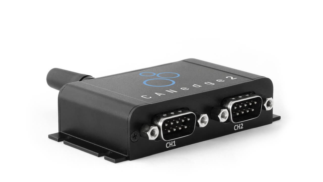 CANedge2 – Dual CAN Bus Telematics Dongle CANEDGE2 – PRO CAN IoT LOGGER
[