Demystifying the OBD2 Connector Pinout Diagram for Automotive Diagnostics and Data Access
Are you diving into the world of automotive diagnostics or looking to tap into your vehicle’s data? Understanding the OBD2 (On-Board Diagnostics II) system is crucial, and at the heart of it lies the 16-pin OBD2 connector. This standardized port is your gateway to a wealth of vehicle information, and deciphering its pinout diagram is the first step to unlocking that potential.
This guide provides a comprehensive and practical exploration of the Obd2 Pinout Diagram. We’ll break down each pin’s function, explore different connector types, and explain how this knowledge is essential for everything from basic diagnostics to advanced data logging.
Learn why understanding the OBD2 pinout diagram is fundamental for anyone working with modern vehicle systems.
You can also watch our OBD2 intro video or get the PDF guide for offline access.
In this article
Author: Martin Falch (updated January 2025)
Download as PDF
Understanding the OBD2 Connector and Pinout Diagram
The OBD2 system is a standardized self-diagnostic system built into virtually all modern vehicles. It allows access to diagnostic trouble codes (DTCs) and real-time data streams through a standardized 16-pin connector, commonly referred to as the OBD2 port or Data Link Connector (DLC). The OBD2 pinout diagram is the schematic that maps each of these 16 pins to specific functions, communication protocols, and power supplies.
You’ve likely encountered the OBD2 system whenever you’ve seen the check engine light or malfunction indicator light on your dashboard. This light signals an issue detected by your car’s onboard computer. Mechanics use OBD2 scanners to interface with your vehicle’s computer system via the OBD2 port, diagnosing problems and accessing valuable data.
Connecting an OBD2 reader to the OBD2 16 pin connector, typically located near the steering wheel, allows tools to send ‘OBD2 requests’ and receive ‘OBD2 responses’. These responses can include parameters like speed, engine RPM, fuel level, and crucially, Diagnostic Trouble Codes (DTCs), enabling efficient troubleshooting and vehicle health monitoring.
Understanding OBD2 for Vehicle Diagnostics: The malfunction indicator light (MIL) often prompts the use of OBD2 scan tools to diagnose car issues.
Does Your Car Have an OBD2 Connector?
Almost certainly, yes!
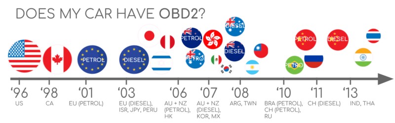
Nearly all non-electric vehicles manufactured after the mid-1990s are OBD2 compliant. While most modern cars utilize the CAN bus protocol for OBD2 communication, older vehicles might employ different protocols even if they feature a 16-pin OBD2 connector. It’s important to note that the presence of a 16-pin connector doesn’t automatically guarantee OBD2 compliance. To confirm, consider the vehicle’s origin and manufacturing date:
OBD2 Compliance Timeline: This chart illustrates the mandated adoption of OBD2 in vehicles based on region and vehicle type.
A Brief History of OBD2 and the Pinout Standard
OBD2’s origins trace back to California, where the California Air Resources Board (CARB) mandated OBD systems in new cars from 1991 onwards for emission control. The Society of Automotive Engineers (SAE) played a crucial role in standardizing OBD2, particularly the DTCs and the OBD connector itself, documented under standard SAE J1962. This standardization included the crucial OBD2 pinout diagram, ensuring interoperability across different vehicle manufacturers.
The OBD2 standard was implemented gradually:
- 1996: OBD2 became mandatory in the USA for gasoline-powered cars and light trucks.
- 2001: The EU required OBD2 for gasoline cars.
- 2003: The EU extended the requirement to diesel cars (EOBD – European On-Board Diagnostics).
- 2005: OBD2 was mandated in the US for medium-duty vehicles.
- 2008: US vehicles were required to use ISO 15765-4 (CAN) as the foundation for OBD2 communication.
- 2010: OBD2 became mandatory for heavy-duty vehicles in the US.
OBD2 Historical Context: Emission control standards and regulatory bodies have driven the evolution and adoption of OBD2 systems.
OBD2 Timeline: Key milestones in the development and implementation of OBD2, from its inception to widespread adoption.
Future of OBD: OBD3 envisions remote diagnostics and integration with cloud and IoT technologies for enhanced vehicle monitoring.
The Future Landscape of OBD2
While OBD2 remains a vital standard, its future is evolving.
Originally designed for emissions testing, legislative OBD2 requirements don’t extend to electric vehicles. Consequently, most modern EVs don’t natively support standard OBD2 requests, often opting for OEM-specific UDS communication. Decoding EV data often requires reverse engineering, as highlighted in case studies for brands like Tesla, Hyundai/Kia, Nissan, and VW/Skoda EVs.
Limitations in data richness and protocol flexibility have spurred the development of alternatives like WWH-OBD (World Wide Harmonized OBD) and OBDonUDS (OBD on UDS). These advancements aim to modernize OBD communication by utilizing the UDS protocol as a foundation. For a deeper dive, explore our introduction to UDS.
The rise of connected cars highlights the inefficiencies of manual emission checks. OBD3 proposes integrating telematics into all vehicles, adding radio transponders for wireless transmission of Vehicle Identification Numbers (VINs) and DTCs to central servers for automated monitoring. Devices like the CANedge2 WiFi CAN logger and CANedge3 3G/4G CAN logger already facilitate data transfer via WiFi/cellular. However, privacy concerns pose political challenges to widespread OBD3 adoption.
Concerns are also emerging from car manufacturers regarding third-party access to OBD2 data. Originally intended for repair shop servicing, OBD2 is now extensively used by third parties for real-time data acquisition via OBD2 dongles and CAN loggers. The German car industry, for example, is exploring options to restrict OBD2 functionality during driving, centralizing data collection with manufacturers. This shift aims to enhance security and control ‘automotive big data’, but raises concerns about limiting third-party innovation in OBD2-based services.
EV Data Access: Electric vehicles often deviate from standard OBD2, potentially limiting access to diagnostic and performance data through conventional OBD2 methods.
Deep Dive: The OBD2 Pinout Diagram – Pin by Pin
The OBD2 pinout diagram, as specified in SAE J1962 and ISO 15031-3, outlines the function of each of the 16 pins in the OBD2 connector. Understanding this diagram is crucial for anyone working with OBD2 systems, whether for diagnostics, data logging, or custom applications. Here’s a detailed breakdown:
OBD2 Connector Pinout Diagram (Type A): A detailed view of the 16-pin OBD2 connector, illustrating the standard pin assignments.
Pinout Table and Descriptions:
| Pin | Name | Description | Protocol Dependency |
|---|---|---|---|
| 1 | Manufacturer Discretionary | Often used for manufacturer-specific purposes, may vary widely. | Varies |
| 2 | SAE J1850 Bus+ | Positive line for SAE J1850 VPW and PWM protocols. | SAE J1850 |
| 3 | Manufacturer Discretionary | Often used for manufacturer-specific purposes, may vary widely. | Varies |
| 4 | Chassis Ground | Ground connection for the vehicle chassis. | All |
| 5 | Signal Ground | Signal ground reference for OBD2 communication. | All |
| 6 | CAN High (CAN-H) | High signal line for CAN bus communication (ISO 15765-4). | ISO 15765-4 |
| 7 | ISO 9141-2 K-Line | K-Line for ISO 9141-2 and ISO 14230-4 (KWP2000) protocols. | ISO 9141-2, ISO 14230-4 |
| 8 | Manufacturer Discretionary | Often used for manufacturer-specific purposes, may vary widely. | Varies |
| 9 | Manufacturer Discretionary | Often used for manufacturer-specific purposes, may vary widely. | Varies |
| 10 | SAE J1850 Bus- | Negative line for SAE J1850 VPW and PWM protocols. | SAE J1850 |
| 11 | Manufacturer Discretionary | Often used for manufacturer-specific purposes, may vary widely. | Varies |
| 12 | Manufacturer Discretionary | Often used for manufacturer-specific purposes, may vary widely. | Varies |
| 13 | Manufacturer Discretionary | Often used for manufacturer-specific purposes, may vary widely. | Varies |
| 14 | CAN Low (CAN-L) | Low signal line for CAN bus communication (ISO 15765-4). | ISO 15765-4 |
| 15 | ISO 9141-2 L-Line | L-Line for ISO 9141-2 and ISO 14230-4 (KWP2000) protocols. | ISO 9141-2, ISO 14230-4 |
| 16 | Battery Power | Provides battery voltage (12V or 24V) for OBD2 devices. | All |

Key Observations from the OBD2 Pinout:
- Power (Pins 16, 4, 5): Pin 16 provides battery power, essential for powering OBD2 devices. Pins 4 and 5 are ground connections, ensuring a stable electrical circuit.
- CAN Bus (Pins 6, 14): Pins 6 (CAN-H) and 14 (CAN-L) are the most commonly used for modern OBD2 communication, as CAN bus is the dominant protocol (ISO 15765-4).
- Legacy Protocols (Pins 2, 7, 10, 15): Pins 2 & 10 (SAE J1850) and 7 & 15 (ISO 9141-2/KWP2000) are for older communication protocols, less frequently used in newer vehicles but still relevant for backward compatibility.
- Manufacturer Discretion (Pins 1, 3, 8, 9, 11, 12, 13): A significant number of pins are reserved for manufacturer-specific use. Their functions can vary widely between vehicle makes and models and are generally not standardized.
Locating the OBD2 Connector:
The OBD2 connector is typically located within the passenger compartment of the vehicle, often within reach of the driver’s seat. Common locations include:
- Under the dashboard on the driver’s side.
- Below the steering column.
- In the center console area.
- Behind an ashtray or small panel.
While standardized in pin count and general location area, the exact placement can vary. If you’re unsure, consult your vehicle’s owner’s manual for the specific OBD2 connector location.
OBD2 Connector Types: Type A vs. Type B
While the OBD2 pinout diagram remains largely consistent, you may encounter two physical connector types: Type A and Type B. Type A is standard in most passenger cars and light-duty vehicles, while Type B is more common in medium and heavy-duty vehicles.
The primary difference lies in the voltage supply and a physical keying feature:
OBD2 Connector Types A & B: Visual comparison highlighting the keying difference and voltage distinctions between Type A (12V) and Type B (24V) connectors.
- Type A: Provides 12V power supply on Pin 16, suitable for cars and light vehicles.
- Type B: Provides 24V power supply on Pin 16, designed for trucks and heavy-duty applications. Type B connectors feature an interrupted groove in the middle, acting as a physical key.
A Type B OBD2 adapter cable is designed to be compatible with both Type A and Type B sockets due to the interrupted groove, while a Type A adapter will not physically fit into a Type B socket. This physical difference helps prevent accidental use of 12V adapters in 24V systems, which could damage devices.
OBD2 Standards: The Foundation of Communication
On-board diagnostics OBD2 operates as a higher layer protocol, much like a language, built upon a communication method like CAN bus (similar to a phone line). This structure parallels other CAN-based higher-layer protocols such as J1939, CANopen, and NMEA 2000.
The OBD2 standards comprehensively define the OBD2 connector pinout, lower-layer communication protocols, OBD2 parameter IDs (PIDs), and more. These standards can be categorized within a 7-layer OSI model framework. Notably, both SAE (primarily for US standards) and ISO (for EU and international standards) contribute to defining these layers. Many standards are technically equivalent, such as SAE J1979 versus ISO 15031-5 and SAE J1962 versus ISO 15031-3, with the latter directly concerning the OBD2 pinout diagram.
OBD2 and CAN Bus in the OSI Model: Illustrates how OBD2 and CAN bus standards map to the 7-layer OSI model, showcasing the layered communication architecture.
OBD2 vs. CAN Bus: A comparative view of OBD2 as a higher-layer protocol built on the foundation of CAN bus for vehicle communication.
OBD2 and CAN Bus: ISO 15765-4
Since 2008, CAN bus (Controller Area Network) has been the mandated lower-layer protocol for OBD2 in all vehicles sold in the US, as per ISO 15765. ISO 15765-4, also known as Diagnostics over CAN (DoCAN), specifies constraints and guidelines for using CAN bus within the OBD2 framework. It focuses on standardizing the CAN interface for diagnostic equipment at the physical, data link, and network layers:
- CAN Bit-rate: Must be either 250 Kbps or 500 Kbps.
- CAN Identifiers: Supports both 11-bit (standard) and 29-bit (extended) CAN IDs.
- Specific CAN IDs: Defines reserved CAN IDs for OBD requests and responses.
- Data Frame Length: Diagnostic CAN frames are limited to 8 bytes of data payload.
- Adapter Cable Length: OBD2 adapter cables must not exceed 5 meters in length.
OBD2 CAN Identifiers (11-bit and 29-bit)
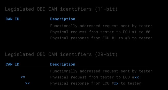
OBD2 communication relies on a request-response message exchange. In most passenger vehicles, 11-bit CAN IDs are used for OBD2. The ‘Functional Addressing’ ID, 0x7DF, is used to query all OBD2-compliant ECUs (Electronic Control Units) for data related to a requested parameter, as defined in ISO 15765-4. ‘Physical Addressing’ requests, using CAN IDs 0x7E0-0x7E7, target specific ECUs but are less commonly used in generic OBD2 scans.
ECUs respond using 11-bit IDs in the range of 0x7E8-0x7EF. The most frequent response ID is 0x7E8 (from the ECM – Engine Control Module), followed by 0x7E9 (TCM – Transmission Control Module).
In some vehicle types, particularly vans and medium/heavy-duty vehicles, OBD2 communication may utilize extended 29-bit CAN identifiers instead of 11-bit. In these cases, the ‘Functional Addressing’ CAN ID becomes 0x18DB33F1. Corresponding responses are typically observed with CAN IDs ranging from 0x18DAF100 to 0x18DAF1FF, commonly 0x18DAF110 and 0x18DAF11E. These 29-bit IDs are sometimes represented in ‘J1939 PGN’ format, specifically PGN 0xDA00 (55808), which J1939-71 standard marks as ‘Reserved for ISO 15765-2’.
OBD2 Request-Response Framework: Depicts the flow of OBD2 communication, from request initiation to data parameter responses.
OBD2 vs. Proprietary CAN: Illustrates the distinction between standardized OBD2 data and OEM-specific CAN data within a vehicle network.
OBD2 vs. Proprietary CAN Protocols
It’s crucial to understand that vehicle ECUs primarily operate using OEM-specific CAN protocols, not OBD2. Each manufacturer implements proprietary CAN communication for core vehicle functions, often unique to brand, model, and year. This OEM-specific CAN data is typically undecipherable without manufacturer documentation or reverse engineering efforts.
Connecting a CAN bus data logger to the OBD2 connector may capture OEM-specific CAN data, typically broadcast at high rates (1000-2000 frames/second). However, many modern vehicles incorporate a ‘gateway’ module that restricts OBD2 port access solely to OBD2 communication, blocking access to the underlying OEM CAN data.
Think of OBD2 as an additional higher-layer protocol operating alongside the OEM-specific protocol. The OBD2 pinout diagram provides access to this standardized diagnostic interface, but not necessarily to the deeper, proprietary vehicle network data.
Bit-rate and ID Validation
OBD2 over CAN can operate with two bit-rates (250K, 500K) and two CAN ID lengths (11-bit, 29-bit), resulting in four possible combinations. Modern cars commonly use 500 Kbps and 11-bit IDs. Diagnostic tools should systematically determine the correct combination for reliable communication.
ISO 15765-4 outlines a systematic initialization sequence for identifying the correct bit-rate and CAN ID configuration. This process leverages the requirement that OBD2-compliant vehicles must respond to a specific mandatory OBD2 request (detailed in the OBD2 PID section) and detects CAN error frames that occur when using an incorrect bit-rate.
Newer versions of ISO 15765-4 account for OBD communication via OBDonUDS (OBD on Unified Diagnostic Services) in addition to OBDonEDS (OBD on Emission Diagnostic Service). While this article primarily focuses on OBD2/OBDonEDS (ISO 15031-5/SAE J1979), WWH-OBD/OBDonUDS (ISO 14229, ISO 27145-3/SAE J1979-2) is increasingly relevant, especially in EU trucks and buses.
To differentiate between OBDonEDS and OBDonUDS, diagnostic tools may send additional UDS requests using 11-bit/29-bit functional address IDs for service 0x22 and data identifier (DID) 0xF810 (protocol identification). Vehicles supporting OBDonUDS should have ECUs that respond to this DID.
In practice, OBDonEDS (also known as OBD2, SAE OBD, EOBD, or ISO OBD) prevails in most non-electric vehicles, while WWH-OBD is primarily found in EU commercial vehicles.
OBD2 Bit-rate and CAN ID Validation Flowchart: A visual guide to the process of validating and determining the correct communication parameters for OBD2.
OBD2 Protocol Standards: An overview of the five main lower-layer protocols used in OBD2, including CAN, KWP2000, ISO 9141, and SAE J1850 variants.
Five Lower-Layer OBD2 Protocols
While CAN bus (ISO 15765) is now dominant for OBD2, especially in vehicles from 2008 onwards, older vehicles may use one of four other lower-layer protocols. Understanding these protocols and their corresponding OBD2 pinout diagram configurations can be helpful when working with pre-2008 vehicles. The pinout can sometimes indicate the protocol in use:
- ISO 15765 (CAN bus): Mandatory in US cars since 2008, now widely adopted. Pins 6 & 14 in the OBD2 pinout diagram are CAN-H and CAN-L respectively.
- ISO 14230-4 (KWP2000): Keyword Protocol 2000, common in 2003+ vehicles, especially in Asia. Pin 7 (K-Line) and optionally Pin 15 (L-Line) are used in the OBD2 pinout diagram.
- ISO 9141-2: Used in EU, Chrysler, and Asian vehicles (2000-2004). Similar pin usage to KWP2000 in the OBD2 pinout diagram: Pin 7 (K-Line) and optionally Pin 15 (L-Line).
- SAE J1850 (VPW – Variable Pulse Width Modulation): Primarily used in older GM vehicles. Pins 2 (Bus+) and 10 (Bus-) are used in the OBD2 pinout diagram.
- SAE J1850 (PWM – Pulse Width Modulation): Predominantly used in older Ford vehicles. Pins 2 (Bus+) and 10 (Bus-) are also used, similar to VPW, in the OBD2 pinout diagram.
Transporting OBD2 Messages via ISO-TP (ISO 15765-2)
All OBD2 data communication over CAN bus utilizes ISO-TP (ISO 15765-2), the ISO Transport Protocol. This protocol enables the transmission of data payloads exceeding the 8-byte limit of a standard CAN frame. ISO-TP is essential for OBD2 functions like retrieving the Vehicle Identification Number (VIN) or Diagnostic Trouble Codes (DTCs), where data often exceeds 8 bytes. It handles segmentation, flow control, and reassembly of larger messages. For more details, refer to our introduction to UDS.
However, many OBD2 data requests and responses fit within a single CAN frame. In these cases, ISO 15765-2 specifies the use of ‘Single Frame’ (SF) messages. The first byte of the data payload (PCI field – Protocol Control Information) indicates the payload length (excluding padding), leaving 7 bytes for OBD2-specific data.
ISO-TP Frame Types for OBD2: Illustrates the different frame types defined by ISO-TP for OBD2 communication, including Single Frame, First Frame, Consecutive Frame, and Flow Control Frame.
The OBD2 Diagnostic Message: Structure and Interpretation
To effectively work with OBD2 over CAN, it’s vital to understand the structure of an OBD2 message within a CAN frame. In simplified terms, an OBD2 message consists of a CAN identifier, a data length indicator (PCI field), and the actual data payload. The payload itself is structured into Mode, Parameter ID (PID), and data bytes.
OBD2 Message Structure: A breakdown of the components within an OBD2 CAN message, including CAN ID, PCI field, Mode, PID, and data bytes.
Example: OBD2 Request and Response – Vehicle Speed
Consider a practical example: requesting vehicle speed. An external tool sends a request message to the vehicle with CAN ID 0x7DF and a 2-byte payload: Mode 0x01 and PID 0x0D. The vehicle responds using CAN ID 0x7E8 with a 3-byte payload. The vehicle speed value is encoded in the fourth byte of the CAN data frame (third byte of the OBD2 payload), in this case, 0x32 (decimal 50).
By consulting the OBD2 PID specifications for PID 0x0D, we can determine that this value represents vehicle speed in km/h. Thus, 0x32 corresponds to 50 km/h. Understanding the OBD2 pinout diagram is the first step, but interpreting the data transmitted requires knowledge of these message structures and PID definitions.
OBD2 Request-Response Example (Speed): A CAN bus trace illustrating a request for vehicle speed (PID 0x0D) and the corresponding response from the vehicle.
OBD2 PID 0x0D – Vehicle Speed: Details the structure and interpretation of OBD2 PID 0x0D, which provides vehicle speed data.
OBD2 Service Modes: An overview of the 10 standardized OBD2 service modes (or modes), each designed for specific diagnostic functions.
The 10 OBD2 Services (Modes)
OBD2 defines 10 diagnostic services, also referred to as modes, each serving a specific purpose. Mode 0x01 is used for retrieving real-time data parameters, while other modes facilitate access to diagnostic trouble codes (DTCs), freeze frame data, clearing DTCs, and more.
It’s important to note that vehicles are not required to support all 10 OBD2 modes. Furthermore, manufacturers may implement OEM-specific modes beyond the 10 standardized ones.
In OBD2 messages, the service mode is indicated in the second byte of the payload. In a request message, the mode is included directly (e.g., 0x01). In a response message, 0x40 is added to the requested mode value (e.g., a response to mode 0x01 will have mode value 0x41).
OBD2 Parameter IDs (PIDs)
Within each OBD2 service mode, Parameter IDs (PIDs) are used to specify the particular data parameter being requested or reported.
For example, Mode 0x01, which provides real-time data, includes approximately 200 standardized PIDs. These PIDs cover a wide range of parameters such as vehicle speed, engine RPM, coolant temperature, fuel level, and many others. However, a vehicle is not obligated to support all PIDs within a given mode. In practice, most vehicles support only a subset of the available PIDs.
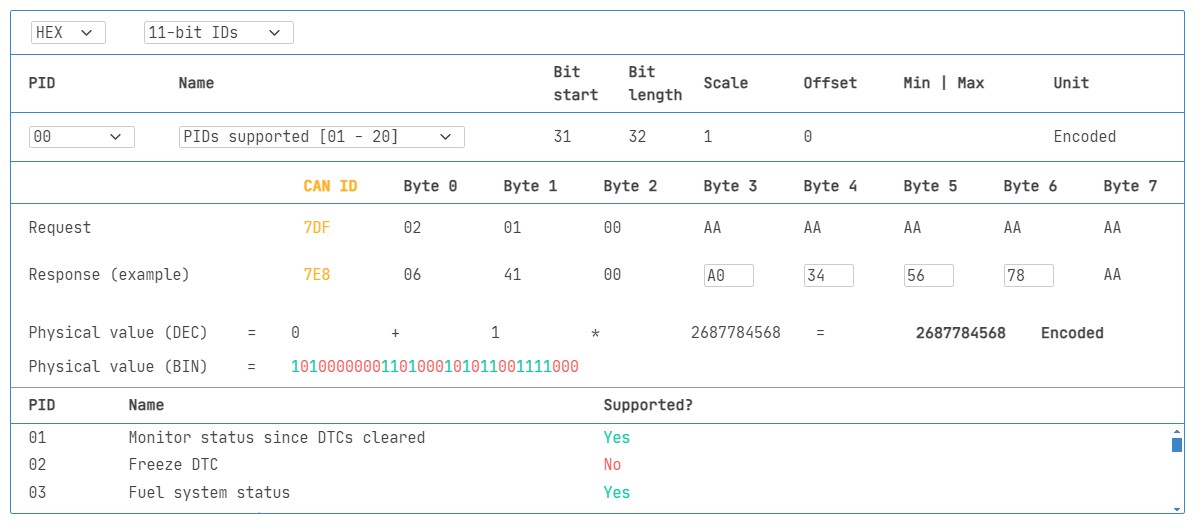
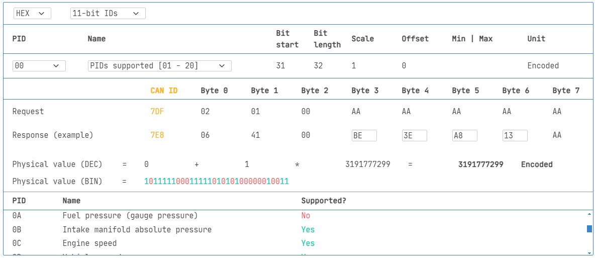
One PID holds special significance: Mode 0x01 PID 0x00. If an emissions-related ECU supports any OBD2 services at all, it must support Mode 0x01 PID 0x00. Responding to this PID, the ECU indicates which PIDs within the range 0x01-0x20 it supports. This makes PID 0x00 a fundamental tool for testing OBD2 compatibility. Similarly, PIDs 0x20, 0x40, 0x60, 0x80, 0xA0, and 0xC0 can be used to query support for subsequent PID ranges in Mode 0x01.
OBD2 Request-Response with PIDs: Emphasizes the role of Parameter IDs (PIDs) in specifying data requests and responses within the OBD2 framework.
OBD2 PID Overview Tool: A screenshot of a tool designed to help users explore and understand OBD2 PIDs within service mode 0x01.
Tip: OBD2 PID Overview Tool
The appendices of SAE J1979 and ISO 15031-5 provide detailed scaling and conversion formulas for standard OBD2 PIDs, enabling the conversion of raw data values into physical units. Our OBD2 PID overview tool simplifies working with Mode 0x01 PIDs. It assists in constructing OBD2 request frames and dynamically decodes OBD2 responses, making data interpretation easier.
OBD2 PID overview tool
Practical Guide: Logging and Decoding OBD2 Data
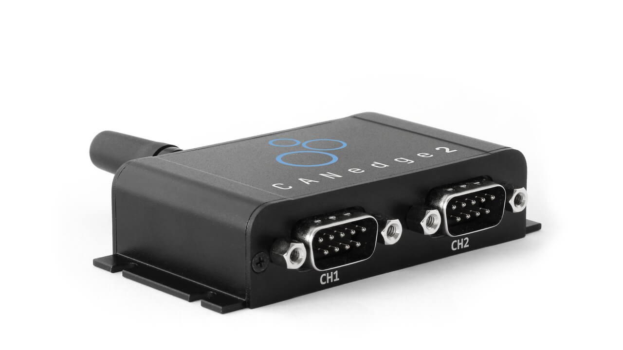
Let’s illustrate how to log OBD2 data practically using the CANedge CAN bus data logger. The CANedge allows custom CAN frame transmission, making it suitable for OBD2 request-response logging. Connect the CANedge to your vehicle via an OBD2-DB9 adapter cable.
OBD2 Data Logger Setup: Illustrates the connection of an OBD2 data logger to a vehicle’s OBD2 port, showing the flow of request and response messages.
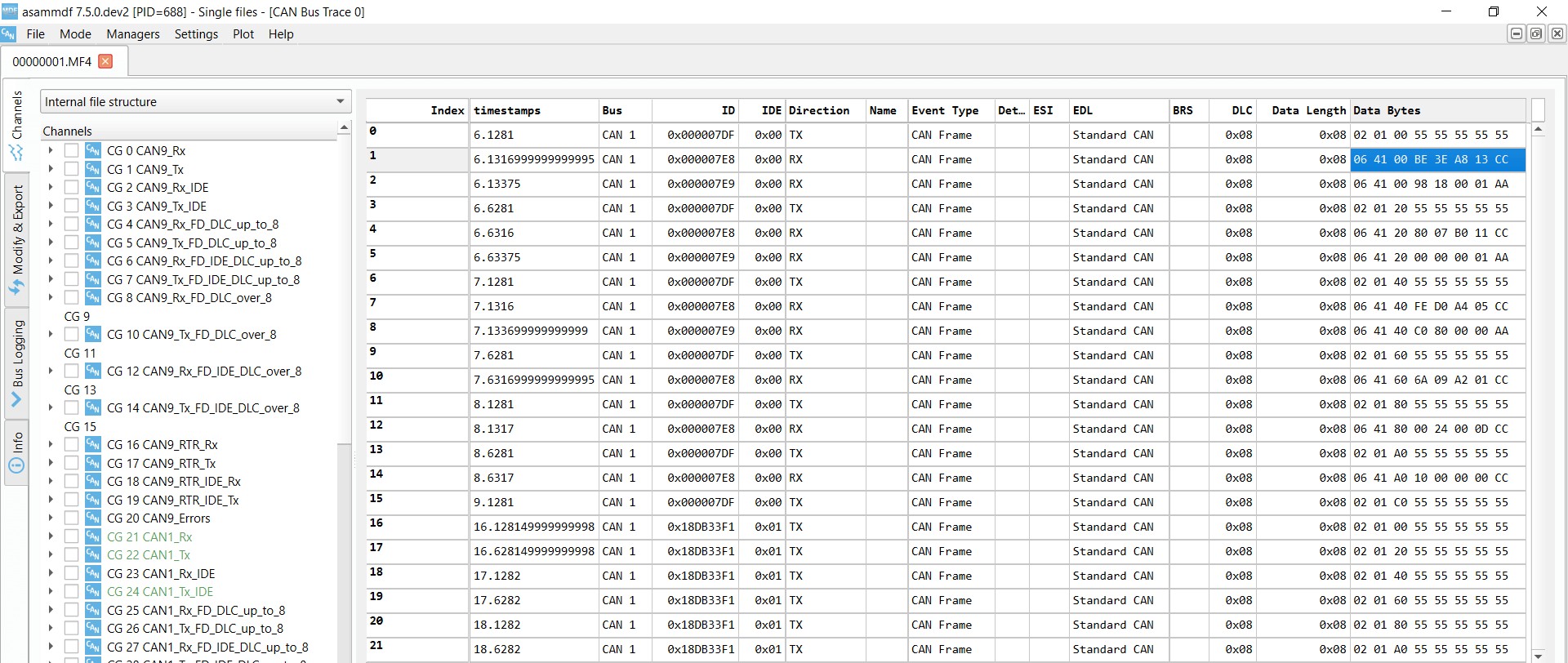
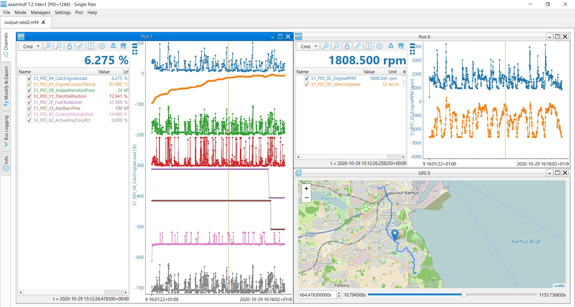
Supported PID Responses: Reviewing responses to ‘Supported PIDs’ requests using software like asammdf to identify vehicle-supported parameters.
Step #1: Bit-rate, ID, and Supported PID Testing
ISO 15765-4 provides a procedure to identify the bit-rate and CAN IDs used by a vehicle. Perform these tests with the CANedge:
- Bit-rate Test: Transmit a CAN frame at 500 Kbps. If successful, use 500 Kbps; otherwise, try 250 Kbps.
- Bit-rate Confirmation: Use the identified bit-rate for subsequent communication.
- Supported PIDs Discovery: Send ‘Supported PIDs’ requests (Mode 0x01 PID 0x00) and analyze responses.
- CAN ID Type Determination: Based on response IDs, determine if 11-bit or 29-bit CAN IDs are in use.
- Supported PID List: Analyze response data to identify the PIDs supported by the vehicle.
Plug-and-play CANedge configurations are available to automate these tests. Most post-2008 non-EV vehicles typically support 40-80 PIDs using 500 Kbps, 11-bit CAN IDs, and the OBD2/OBDonEDS protocol.
As illustrated in the asammdf GUI screenshot, multiple ECUs may respond to a single OBD request when using the functional address 0x7DF. Since all OBD2/OBDonEDS compliant ECUs must support service 0x01 PID 0x00, multiple responses are common for this PID. Subsequent ‘Supported PIDs’ requests usually elicit fewer responses as fewer ECUs support the extended PID ranges. The ECM (0x7E8) often supports all PIDs supported by other ECUs in the system. To reduce bus load, consider using ‘Physical Addressing’ with CAN ID 0x7E0 to target the ECM directly for subsequent requests.
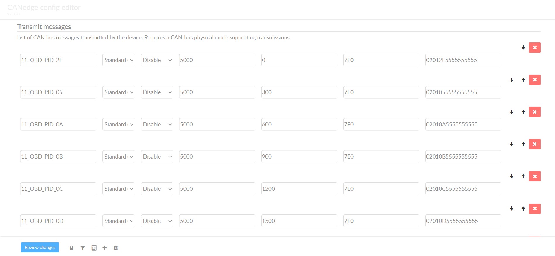
Step #2: Configuring OBD2 PID Requests
Once you’ve identified supported PIDs, bit-rate, and CAN IDs, configure your data logger to request the desired PIDs. Consider these points:
- CAN Addressing: Switch to ‘Physical Addressing’ request IDs (e.g., 0x7E0) to minimize redundant responses and bus load.
- Request Spacing: Introduce delays of 300-500 ms between OBD2 requests to prevent ECU overload and ensure reliable responses.
- Power Management: Implement triggers to halt transmissions when the vehicle is inactive, preventing battery drain by avoiding continuous ECU wake-up calls.
- Data Filtering: Apply filters to record only OBD2 responses, particularly if the vehicle network also broadcasts OEM-specific CAN data, to streamline data logs.
With these configurations, your CANedge is set to log raw OBD2 data efficiently.
CANedge OBD2 Request Configuration: An example of a CANedge transmit list configured to request specific OBD2 PIDs for data logging.
OBD2 Data Visualization in asammdf: Example of decoded and visualized OBD2 data in asammdf software, using a DBC file for signal interpretation.
Step #3: DBC Decoding of Raw OBD2 Data
To analyze and visualize logged OBD2 data, you need to decode the raw data into physical values. Decoding specifications are in ISO 15031-5/SAE J1979 and resources like Wikipedia. For convenience, a free OBD2 DBC file is available, simplifying DBC decoding in most CAN bus analysis tools.
Decoding OBD2 data is more complex than standard CAN signal decoding. Different OBD2 PIDs can be transmitted using the same CAN ID (e.g., 0x7E8). Therefore, the CAN ID alone isn’t sufficient to identify the signal within the payload.
Decoding requires considering the CAN ID, OBD2 mode, and OBD2 PID to uniquely identify each signal. This multiplexing technique, known as ‘extended multiplexing‘, is supported by formats like DBC files.
CANedge: Your OBD2 Data Logger
The CANedge offers an easy way to log OBD2 data onto SD cards (8-32 GB). Simply connect to a vehicle to begin logging and utilize free software/APIs and the OBD2 DBC file for data decoding.
OBD2 logger intro CANedge
OBD2 Multi-Frame Examples (ISO-TP)
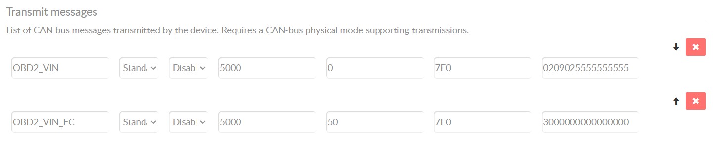
While many examples focus on single-frame OBD2 communication, ISO-TP (ISO 15765-2) is crucial for multi-frame exchanges. Multi-frame communication requires flow control frames. CANedge configurations can manage flow control by transmitting a static flow control frame shortly after the initial request. Analyzing multi-frame OBD2 responses requires CAN software and APIs that support ISO-TP, such as CANedge MF4 decoders.
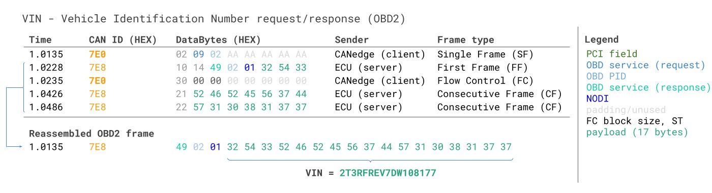
OBD2 Multi-Frame Request Example: Requesting the Vehicle Identification Number (VIN) using a multi-frame OBD2 request message.
Example 1: OBD2 Vehicle Identification Number (VIN) Retrieval
The Vehicle Identification Number (VIN) is essential for telematics and diagnostics. Retrieve the VIN using OBD2 mode 0x09 and PID 0x02:
The test tool initiates a Single Frame request with PCI field 0x02, service ID 0x09, and PID 0x02. The vehicle responds with a First Frame containing PCI, length (0x014 = 20 bytes), mode (0x49), and PID (0x02). Following the PID is the Number Of Data Items (NODI) byte (0x01 in this case), indicating one VIN is being returned. The subsequent 17 bytes represent the VIN, which can be converted from HEX to ASCII.
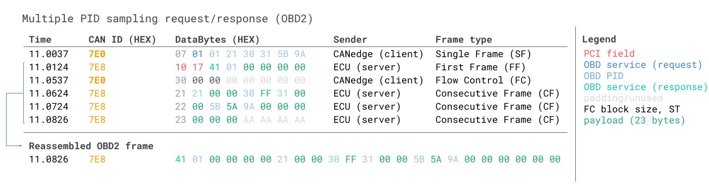
Example 2: OBD2 Multi-PID Request (6x)
OBD2 allows requesting up to 6 Mode 0x01 PIDs in a single request frame. The ECU responds with data for supported PIDs, potentially using multi-frame responses via ISO-TP. While efficient, this method complicates signal decoding, especially with generic OBD2 DBC files, due to the request-specific signal encoding.
Decoding multi-PID responses via generic DBC files is challenging. The payload structure is request-dependent, making DBC generalization difficult across vehicles with varying PID support. DBC files would need to account for PID-specific payload positions, complicating cross-vehicle compatibility. For complex multi-PID requests, consider custom scripts or tools that correlate responses with requests, rather than relying solely on generic DBC files.
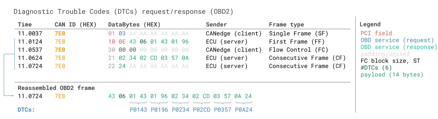
Example 3: OBD2 Diagnostic Trouble Codes (DTCs)
OBD2 mode 0x03 (‘Show stored Diagnostic Trouble Codes’) retrieves emissions-related DTCs. The request frame contains only the mode (0x03), without a PID. Responding ECUs report the number of stored DTCs (including zero if none are present), with each DTC encoded in 2 bytes. Multi-frame responses are necessary if more than two DTCs are stored.
Each 2-byte DTC value is structured according to ISO 15031-5/ISO 15031-6. The first two bits define the DTC category (e.g., Powertrain, Body, Chassis, Network), and the remaining 14 bits form a 4-digit hexadecimal code. Decoded DTC values can be looked up in OBD2 DTC databases like repairpal.com.
OBD2 DTC Decoding Structure: Illustrates the 2-byte structure of a DTC, including the category bits and the 4-digit hexadecimal code, for interpretation and lookup.
OBD2 Data Logging: Use Case Examples
OBD2 data logging has diverse applications across various sectors:
Car Data Logging
OBD2 data from cars can be used for fuel efficiency analysis, driver behavior improvement, prototype testing, and insurance telematics.
obd2 logger
Real-time Car Diagnostics
OBD2 interfaces facilitate real-time streaming of vehicle data for live diagnostics and troubleshooting.
obd2 streaming
Predictive Maintenance
IoT-enabled OBD2 loggers enable remote vehicle monitoring for predictive maintenance, reducing downtime and preventing breakdowns.
predictive maintenance
Vehicle Black Box Logging
OBD2 loggers serve as ‘black boxes’ in vehicles, capturing crucial data for incident analysis, warranty validation, and diagnostic purposes.
can bus blackbox
Do you have an OBD2 data logging application? Contact us for expert consultation.
Contact us
Explore more guides in our tutorials section or download the comprehensive ‘Ultimate Guide’ PDF.
Ready to Log or Stream OBD2 Data?
Get Your OBD2 Data Logger Today!
Buy now Contact us
Recommended for You
OBD2 DATA LOGGER: EASILY LOG & CONVERT OBD2 DATA
CANEDGE2 – PRO CAN IoT LOGGER
[