Need a deep dive into the OBD2 ISO CAN Bus protocol?
This comprehensive guide provides an in-depth exploration of the On-Board Diagnostic (OBD2) protocol, focusing on its implementation over the Controller Area Network (CAN bus) as defined by the ISO 15765 standard. We’ll dissect the OBD2 connector, Parameter IDs (PIDs), and the crucial role of CAN bus in modern vehicle diagnostics.
This is more than just a simple introduction; it’s a detailed tutorial designed to equip you with the knowledge to understand, request, and decode OBD2 data transmitted via the ISO CAN bus protocol. Whether you’re a seasoned automotive technician, an engineering student, or a car enthusiast, this guide will elevate your understanding of vehicle diagnostics.
Learn why this article is becoming the go-to resource for mastering the OBD2 ISO CAN bus protocol.
You can also enhance your learning with visual aids by watching our OBD2 introduction video above – or get the PDF for offline access.
Understanding the OBD2 ISO CAN Bus Protocol
What is OBD2 and its Significance?
OBD2, short for On-Board Diagnostics version 2, is a standardized system integrated into modern vehicles. It acts as the vehicle’s self-diagnostic and reporting system. The OBD2 protocol enables access to crucial diagnostic trouble codes (DTCs) and real-time vehicle data through a standardized OBD2 connector.
You’ve likely encountered OBD2 in everyday driving. The malfunction indicator light, commonly known as the “check engine light,” is a direct output of the OBD2 system. When this light illuminates, it signals that the vehicle’s computer has detected an issue.
Mechanics and technicians rely on OBD2 scanners to interpret these signals and diagnose problems efficiently. These scanners connect to the OBD2 16 pin connector, typically located within easy reach under the dashboard near the steering wheel. The OBD2 scanner sends standardized ‘OBD2 requests’ to the vehicle’s electronic control units (ECUs). In response, the car transmits ‘OBD2 responses’ containing valuable data such as speed, engine temperature, fuel level, and DTCs. This streamlined communication significantly accelerates the troubleshooting and repair process.
Understanding OBD2: On-Board Diagnostics and the Malfunction Indicator Light (MIL)
OBD2 Compatibility: Does Your Car Support It?
The answer for most modern, non-electric vehicles is a resounding Yes!
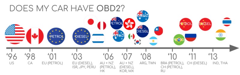
OBD2 has become a near-universal standard. The vast majority of cars manufactured after the mid-1990s support OBD2, and most of these implementations utilize the CAN bus for communication. However, for older vehicles, the presence of a 16-pin OBD2 connector doesn’t automatically guarantee OBD2 compliance. Some older models may have the connector but not fully adhere to the OBD2 protocol. A key indicator of OBD2 compliance is the vehicle’s year and region of purchase:
OBD2 Compliance Guide: Determine if Your Car Supports OBD2 Based on Region and Year
A Brief History of OBD2 and the ISO CAN Bus Protocol
The genesis of OBD2 can be traced back to California and the California Air Resources Board (CARB). In the pursuit of stricter emission controls, CARB mandated OBD in all new vehicles starting from 1991.
The Society of Automotive Engineers (SAE) played a crucial role in standardizing OBD2. They recommended the OBD2 standard, leading to the standardization of DTCs and the physical OBD connector across different vehicle manufacturers through the SAE J1962 standard.
The adoption of the OBD2 standard was a phased process:
- 1996: OBD2 became mandatory in the USA for all cars and light trucks.
- 2001: The European Union mandated OBD2 for gasoline cars.
- 2003: OBD2 compliance extended to diesel cars in the EU under the European On-Board Diagnostics (EOBD) regulation.
- 2005: OBD2 became required in the US for medium-duty vehicles.
- 2008: A significant shift occurred as US vehicles were required to implement ISO 15765-4 (CAN) as the foundation for OBD2 communication, standardizing the OBD2 ISO CAN bus protocol.
- 2010: OBD2 standardization was completed in the US with its mandatory implementation in heavy-duty vehicles.
OBD2 History: Evolution from Emission Control to Data Access via CAN bus
OBD2 History Timeline: A Visual Overview of On-Board Diagnostics Evolution
OBD2 Future: The Trajectory Towards OBD3, Remote Diagnostics, and IoT Integration
Future Trends in OBD2 and Vehicle Diagnostics
OBD2 is firmly entrenched in automotive diagnostics, but its evolution continues.
Here are key trends shaping the future of OBD2:
Initially designed for emission control and testing, regulatory OBD2 is facing challenges, particularly with the rise of electric vehicles (EVs). EVs, not being combustion engine-based, are not legally obligated to support OBD2 in its traditional form. In practice, very few modern EVs support standard OBD2 requests. Instead, most utilize OEM-specific UDS (Unified Diagnostic Services) communication protocols. This shift makes accessing and decoding data from EVs considerably more complex, typically requiring reverse engineering efforts. However, progress is being made, as evidenced by case studies on accessing data from EVs like Tesla, Hyundai/Kia, Nissan, and VW/Skoda.
The limitations of current OBD2 implementations, particularly in data richness and lower-layer protocols, have spurred the development of advanced alternatives. WWH-OBD (World Wide Harmonized OBD) and OBDonUDS (OBD on UDS) are emerging as enhancements. These protocols aim to modernize OBD communication by building upon the UDS protocol, offering greater flexibility and data capacity. For a deeper understanding of these advancements, explore our introduction to UDS.
In an increasingly connected world, traditional OBD2 testing methods are becoming less efficient. Manual emission checks are time-consuming and costly.
The proposed solution is OBD3 – the integration of telematics into all vehicles.
OBD3 envisions equipping every car with a small radio transponder, similar to those used for bridge tolls. This technology would enable vehicles to wirelessly transmit their vehicle identification number (VIN) and DTCs via WiFi to a central server for automated monitoring and diagnostics.
Many existing devices already facilitate CAN or OBD2 data transfer via WiFi or cellular networks, such as the CANedge2 WiFi CAN logger and the CANedge3 3G/4G CAN logger.
While OBD3 offers benefits in terms of cost savings and convenience, it also raises political and privacy concerns related to increased vehicle surveillance.
Originally conceived for stationary emission controls, OBD2 has expanded its role significantly. It is now widely used by third parties to generate real-time vehicle data through OBD2 dongles, CAN loggers and other devices. However, the German automotive industry is advocating for changes that could restrict this third-party access [https://www.eenewsautomotive.com/news/german-car-industry-plans-close-obd-interface?news_id=93237]:
“OBD has been designed to service cars in repair shops. In no way has it been intended to allow third parties to build a form of data-driven economy on the access through this interface“
– Christoph Grote, SVP Electronics, BMW (2017)
The proposal involves disabling OBD2 functionality during normal driving, centralizing data collection within manufacturer-controlled servers. This move would give manufacturers greater control over ‘automotive big data’.
Arguments for this shift often cite security benefits, such as reducing the risk of car hacking). However, critics view it as a commercially motivated strategy to monopolize vehicle data [https://www.navixy.com/blog/obd-trackers-what-future-awaits/]. The ultimate impact of this trend on the OBD2 aftermarket and third-party services remains uncertain.
OBD2 Future: The Potential Shift Towards Electric Vehicles Limiting Data Access
Deep Dive into OBD2 Standards and the ISO CAN Bus Protocol
On-board diagnostics OBD2 is a higher-layer protocol, operating conceptually like a language spoken over a communication network. CAN bus, on the other hand, is the communication method itself, akin to a telephone line. This places OBD2 in the same category as other CAN-based higher-layer protocols such as J1939, CANopen, and NMEA 2000.
Specifically, OBD2 standards meticulously define the OBD2 connector, the lower-layer communication protocols, OBD2 Parameter IDs (PIDs), and numerous other aspects of vehicle diagnostics.
These standards can be visualized using the 7-layer OSI model, a conceptual framework for understanding network communication. As you examine the OSI model in the context of OBD2 and CAN bus, you’ll notice that both SAE (Society of Automotive Engineers) and ISO (International Organization for Standardization) standards cover various layers. This reflects the global nature of OBD2 standardization, with SAE standards largely originating in the US and ISO standards gaining prominence internationally, particularly in Europe. Many of these standards are technically equivalent, such as SAE J1979 and ISO 15031-5 for diagnostic services, and SAE J1962 and ISO 15031-3 for the OBD connector. The OBD2 ISO CAN bus protocol specifically refers to the standards defined under ISO 15765, which dictates how OBD2 operates over the CAN bus.
OBD2 vs. CAN Bus: Mapping the ISO 15765 and ISO 11898 Standards to the OSI 7-Layer Model
OBD2 Connector Pinout: Type A Female Socket (Data Link Connector – DLC) Diagram
The OBD2 Connector [SAE J1962 / ISO 15031-3]
The 16-pin OBD2 connector is the physical interface that enables seamless access to your vehicle’s diagnostic data. It is rigorously defined by the SAE J1962 / ISO 15031-3 standards.
The illustration above depicts a Type A OBD2 pin connector, also known as a Data Link Connector (DLC).
Key characteristics of the OBD2 connector include:
- Its location is typically near the steering wheel, though it may be subtly hidden from direct view behind a panel.
- Pin 16 consistently provides battery power, often remaining active even when the ignition is switched off, allowing for diagnostics without the engine running.
- The specific OBD2 pinout configuration is protocol-dependent, varying slightly based on the communication protocol used by the vehicle.
- In vehicles employing the OBD2 ISO CAN bus protocol, pins 6 (CAN-High) and 14 (CAN-Low) are typically connected, facilitating CAN bus communication.
OBD2 Connector Types: A vs. B
You may encounter two primary types of OBD2 connectors: Type A and Type B. Type A connectors are predominantly used in passenger cars and light-duty vehicles, while Type B connectors are more common in medium and heavy-duty vehicles.
While both types share a similar OBD2 pinout structure, they differ in their power supply outputs. Type A connectors typically provide 12V power, whereas Type B connectors supply 24V, reflecting the different electrical systems in various vehicle classes. Baud rates can also vary; cars often use 500 kbps, while heavy-duty vehicles traditionally used 250 kbps (though 500 kbps support is increasingly common).
Visually distinguishing between Type A and Type B OBD2 sockets is straightforward. The Type B OBD2 connector features a distinctive interrupted groove in the center. Consequently, a Type B OBD2 adapter cable is universally compatible with both Type A and Type B sockets. However, a Type A adapter will not physically fit into a Type B socket due to the groove difference.
OBD2 Connector Types A and B: Distinguishing Features and Applications in Cars, Vans, and Trucks (SAE J1962)
OBD2 vs. CAN Bus ISO 15765: Highlighting the Relationship in Vehicle Communication
OBD2 and CAN Bus: The ISO 15765-4 Standard
Since 2008, CAN bus has been mandated as the primary lower-layer protocol for OBD2 in all vehicles sold in the US, as dictated by the ISO 15765 standard, specifically ISO 15765-4. This standard is the cornerstone of the OBD2 ISO CAN bus protocol.
ISO 15765-4, also known as Diagnostics over CAN (DoCAN), imposes a set of specific constraints and guidelines on the CAN standard (ISO 11898) to ensure interoperability and reliable diagnostic communication.
ISO 15765-4 standardizes the CAN interface for diagnostic test equipment, focusing on the physical layer, data link layer, and network layer of the OSI model. Key specifications include:
- CAN bus bit-rate: Must be either 250 kbps or 500 kbps.
- CAN IDs: Supports both 11-bit (standard) and 29-bit (extended) CAN identifiers.
- CAN ID Usage: Defines specific CAN IDs reserved for OBD requests and responses to avoid conflicts with other vehicle communication.
- Diagnostic CAN Frame Data Length: Mandates a fixed data length of 8 bytes for diagnostic CAN frames.
- OBD2 Adapter Cable Length: Limits the maximum length of the OBD2 adapter cable to 5 meters to maintain signal integrity.
OBD2 CAN Identifiers: 11-bit and 29-bit
OBD2 communication over CAN bus relies on a request-response mechanism. Every diagnostic interaction involves an initial request message from a diagnostic tool and a subsequent response message from the vehicle’s ECU.
In most passenger cars, 11-bit CAN IDs are employed for OBD2 communication. In this configuration, the ‘Functional Addressing’ ID is 0x7DF. This ID is used to broadcast a request to all OBD2-compliant ECUs in the vehicle, effectively asking if any ECU has data to report for the requested parameter (as defined in ISO 15765-4). In contrast, CAN IDs within the range of 0x7E0 to 0x7E7 are reserved for ‘Physical Addressing’ requests, which target specific ECUs. Physical addressing is less frequently used in standard OBD2 diagnostics.
ECUs respond to functional or physical requests using 11-bit CAN IDs in the range of 0x7E8 to 0x7EF. The most prevalent response ID is 0x7E8, typically originating from the ECM (Engine Control Module). Another common response ID is 0x7E9, often from the TCM (Transmission Control Module).
In some vehicle categories, particularly vans and light, medium, and heavy-duty vehicles, extended 29-bit CAN identifiers may be used for OBD2 communication instead of the standard 11-bit IDs.
When 29-bit identifiers are used, the ‘Functional Addressing’ CAN ID becomes 0x18DB33F1.
Correspondingly, responses from the vehicle are transmitted with CAN IDs ranging from 0x18DAF100 to 0x18DAF1FF. Common response IDs in this range include 0x18DAF110 and 0x18DAF11E. These 29-bit response IDs are sometimes represented in the ‘J1939 PGN’ format. Specifically, the PGN 0xDA00 (55808) is used, which, according to the J1939-71 standard, is ‘Reserved for ISO 15765-2’, further solidifying the link between OBD2 ISO CAN bus protocol and established automotive networking standards.
OBD2 Protocol Request and Response Frames: Structure and Parameter Data Flow
OBD2 vs. Proprietary CAN bus: Differentiating Standardized and OEM-Specific Vehicle Data
OBD2 vs. Proprietary CAN Protocols: Understanding the Difference
It’s crucial to recognize that vehicle Electronic Control Units (ECUs) operate primarily using proprietary CAN protocols, developed by each Original Equipment Manufacturer (OEM). OBD2 is not the fundamental protocol for core vehicle functions. These OEM-specific CAN protocols are tailored to the particular vehicle brand, model, and production year. Unless you are the OEM or have access to proprietary documentation, interpreting this OEM-specific CAN data is generally not possible without reverse engineering.
When you connect a CAN bus data logger to your vehicle’s OBD2 connector, you may observe OEM-specific CAN data alongside OBD2 data. This OEM data is typically broadcast at high rates, often between 1000-2000 frames per second. However, in many newer vehicles, a ‘gateway’ module acts as a security barrier, blocking access to this raw CAN data through the OBD2 port and exclusively enabling standardized OBD2 communication.
In essence, think of OBD2 as an ‘additional’ higher-layer protocol that operates alongside the OEM-specific protocol. It’s a standardized diagnostic interface layered on top of the vehicle’s native communication network.
Bit-rate and ID Validation in OBD2 ISO CAN Bus Protocol
As defined by the OBD2 ISO CAN bus protocol standards, OBD2 communication can occur using two possible bit-rates (250 kbps, 500 kbps) and two CAN ID lengths (11-bit, 29-bit). This creates four potential combinations for establishing communication. In contemporary vehicles, the most prevalent combination is 500 kbps bit-rate with 11-bit CAN IDs. However, robust external diagnostic tools must systematically verify these parameters to ensure correct communication.
ISO 15765-4 provides detailed recommendations for implementing a systematic initialization sequence to automatically determine the correct combination of bit-rate and CAN ID length for a given vehicle. The process leverages the fact that OBD2-compliant vehicles must respond to a specific mandatory OBD2 request (detailed in the OBD2 PID section) and the principle that transmitting CAN data at an incorrect bit-rate will result in CAN error frames.
More recent versions of ISO 15765-4 acknowledge that vehicles may support OBD communication via either OBDonUDS or OBDonEDS. This article primarily focuses on OBD2/OBDonEDS (OBD on Emission Diagnostic Service as per ISO 15031-5/SAE J1979), which is more common in non-EV cars currently, as opposed to WWH-OBD/OBDonUDS (OBD on Unified Diagnostic Service as per ISO 14229, ISO 27145-3/SAE J1979-2), which is primarily used in EU trucks and buses.
To distinguish between OBDonEDS and OBDonUDS protocol support, a diagnostic tool may send additional request messages, specifically UDS requests with 11-bit or 29-bit functional address IDs for service 0x22 and Data Identifier (DID) 0xF810 (protocol identification). Vehicles that support OBDonUDS are required to have ECUs that respond to this specific DID.
In practical terms, OBDonEDS (also known as OBD2, SAE OBD, EOBD, or ISO OBD) is the predominant standard in most non-electric vehicles today, while WWH-OBD is mainly found in European trucks and buses.
OBD2 Bit-rate and CAN ID Validation Flowchart According to ISO 15765-4 Standard
OBD2 Standards: The Five Lower-Layer Protocols Including CAN (ISO 15765), KWP2000, SAE J1850, and ISO 9141
Five Lower-Layer OBD2 Protocols: Beyond CAN Bus
Today, CAN bus, as specified in ISO 15765, is the dominant lower-layer protocol for OBD2 in the vast majority of vehicles. This is what constitutes the OBD2 ISO CAN bus protocol.
However, when working with older vehicles (pre-2008), it’s beneficial to be aware of the four alternative lower-layer protocols that were previously used as the basis for OBD2 communication. The OBD2 connector pinouts can sometimes provide clues about which protocol might be in use.
- ISO 15765 (CAN bus): Mandatory in US vehicles since 2008 and now the most widely used protocol globally.
- ISO 14230-4 (KWP2000): Keyword Protocol 2000, a common protocol in vehicles from 2003 onwards, particularly in Asia.
- ISO 9141-2: Used in European, Chrysler, and Asian vehicles manufactured in the early 2000s (approximately 2000-2004).
- SAE J1850 (VPW – Variable Pulse Width Modulation): Primarily used in older General Motors (GM) vehicles.
- SAE J1850 (PWM – Pulse Width Modulation): Predominantly used in older Ford vehicles.
ISO-TP: Transporting OBD2 Messages via ISO 15765-2
All OBD2 data communication over CAN bus relies on a transport protocol called ISO-TP (ISO 15765-2). This protocol is essential for enabling the transmission of data payloads that exceed the 8-byte limit of standard CAN frames. ISO-TP is crucial in OBD2 operations such as retrieving the Vehicle Identification Number (VIN) or Diagnostic Trouble Codes (DTCs), which often require more than 8 bytes of data. ISO 15765-2 provides mechanisms for segmentation, flow control, and reassembly of these larger messages. For a comprehensive understanding of ISO-TP, refer to our introduction to UDS, as UDS also utilizes ISO-TP.
In many OBD2 data exchanges, however, the data payload fits within a single CAN frame. In these cases, ISO 15765-2 specifies the use of a ‘Single Frame’ (SF) format. In a Single Frame, the first data byte (known as the PCI field – Protocol Control Information) indicates the payload length (excluding padding), leaving 7 bytes available for the actual OBD2 communication content.
ISO 15765-2 ISO-TP OBD2 Frame Types: Single Frame, First Frame, Consecutive Frame, and Flow Control Frame
The OBD2 Diagnostic Message Structure [SAE J1979, ISO 15031-5]
To gain a deeper understanding of OBD2 communication over CAN, let’s examine the structure of a raw ‘Single Frame’ OBD2 CAN message. In simplified terms, an OBD2 message consists of a CAN identifier, a data length indicator (PCI field), and the data payload itself. The data payload is further structured into three primary components: Mode, Parameter ID (PID), and Data Bytes.
OBD2 PIDs: Breakdown of the OBD-II Message Structure – Mode, PID, and Data Bytes Explained
OBD2 Request/Response Example: Vehicle Speed
Let’s illustrate OBD2 messaging with a practical example: requesting and receiving vehicle speed data.
In this scenario, an external diagnostic tool initiates communication by sending a request message to the vehicle. This request is transmitted with CAN ID 0x7DF and contains a 2-byte payload: Mode 0x01 and PID 0x0D. Mode 0x01 signifies “Show current data,” and PID 0x0D corresponds to “Vehicle Speed.”
The vehicle’s ECU, upon receiving this request, responds with a message via CAN ID 0x7E8. The response payload is 3 bytes long. The crucial data byte in this response is the 4th byte of the CAN data frame, which contains the vehicle speed value. In our example, this byte is 0x32, which is 50 in decimal form.
By consulting the OBD2 PID specification for PID 0x0D, we can determine the decoding rules. For Vehicle Speed (PID 0x0D), the value 0x32 translates to a physical value of 50 km/h. This example demonstrates the fundamental request-response interaction and data interpretation process in OBD2 ISO CAN bus protocol communication.
OBD2 Request 7DF and Response 7E8 Example: Communication Flow for Vehicle Speed Data
OBD2 PID Example: Decoding Vehicle Speed (PID 0D) and Converting to Physical Value
OBD2 Services/Modes: Overview of the 10 Standardized Diagnostic Services – Current Data, Freeze Frame, Clear DTCs, and More
The 10 OBD2 Diagnostic Services (Modes)
The OBD2 standard defines 10 diagnostic services, often referred to as modes. Each mode serves a specific purpose in vehicle diagnostics. Mode 0x01, for instance, is used to retrieve current, real-time data parameters, while other modes are designed for accessing and clearing diagnostic trouble codes (DTCs) or retrieving freeze frame data, which captures vehicle conditions when a DTC was set.
It’s important to note that vehicles are not obligated to support all 10 OBD2 modes. Furthermore, manufacturers may implement additional, non-standardized modes beyond the 10 defined modes. These are known as OEM-specific OBD2 modes and provide access to proprietary diagnostic information.
In OBD2 messages, the mode is encoded in the second byte of the data payload. In a request message, the mode is included directly (e.g., 0x01 for Mode 1). In a response message, a convention is followed where 0x40 is added to the requested mode (e.g., a response to Mode 0x01 will have a mode byte of 0x41).
OBD2 Parameter IDs (PIDs): Accessing Specific Data
Within each OBD2 mode, Parameter IDs (PIDs) are used to specify the exact data parameter being requested or reported.
For example, Mode 0x01 (“Show current data”) encompasses approximately 200 standardized PIDs. These PIDs provide access to a wide range of real-time vehicle data, including parameters like vehicle speed, engine RPM, coolant temperature, and fuel level. However, it’s crucial to understand that a vehicle is not required to support all defined OBD2 PIDs within a given mode. In practice, most vehicles support only a subset of the standardized PIDs.
Among the vast array of PIDs, one PID holds special significance: PID 0x00 in Mode 0x01.
If an emissions-related ECU is OBD2-compliant and supports any OBD2 services, it must support Mode 0x01 PID 0x00. When queried with this PID, the vehicle’s ECU responds by indicating which PIDs in the range of 0x01 to 0x20 it supports. This makes PID 0x00 invaluable as a fundamental ‘OBD2 compatibility test’. Furthermore, PIDs 0x20, 0x40, 0x60, 0x80, 0xA0, and 0xC0 serve a similar purpose, each revealing the ECU’s support for subsequent blocks of PIDs within Mode 0x01 (PIDs 0x21-0x40, 0x41-0x60, and so on).
OBD2 Protocol Request and Response Frames: Illustrating PID Data Parameters
OBD2 PID Overview Tool: Service 01 Interface for Exploring Parameter IDs
OBD2 PID Overview Tool: Your Diagnostic Aid
The appendices of SAE J1979 and ISO 15031-5 standards documents contain essential scaling and conversion information for standard OBD2 PIDs. This information is crucial for correctly decoding raw PID data into meaningful physical values (as explained in our CAN bus introduction).
For quick and convenient lookup of Mode 0x01 PIDs, our OBD2 PID overview tool is an invaluable resource. This tool assists you in constructing OBD2 request frames and dynamically decoding OBD2 responses, streamlining your diagnostic process.
OBD2 PID overview tool
Access the OBD2 PID Overview Tool for Efficient Diagnostic Lookups
Practical Guide: Logging and Decoding OBD2 Data
This section provides a practical, step-by-step guide on how to log OBD2 data using the CANedge CAN bus data logger.
The CANedge is a versatile tool that allows you to configure custom CAN frames for transmission, making it ideally suited for OBD2 data logging applications.
Once configured, the CANedge can be easily connected to your vehicle’s OBD2 port using our OBD2-DB9 adapter cable.
OBD2 PID Data Logger Request: Example of 7DF and 7E8 CAN ID Communication
Validating Bit-rate: Test Successful CAN Frame Transmission at 500K
Supported PIDs Validation: Reviewing Responses in asammdf for OBD2 Compliance
Step #1: Bit-rate, ID, and Supported PID Validation
As previously discussed, ISO 15765-4 outlines a procedure for determining the correct bit-rate and CAN IDs used by a specific vehicle for OBD2 ISO CAN bus protocol communication. You can use the CANedge to perform these validation steps:
- Bit-rate Test: Begin by sending a CAN frame at 500 kbps. Monitor to confirm successful transmission. If unsuccessful, repeat the test at 250 kbps.
- Bit-rate Confirmation: Use the successfully tested bit-rate for all subsequent OBD2 communication with the vehicle.
- Supported PIDs Discovery: Send multiple ‘Supported PIDs’ requests (Mode 0x01 PID 0x00, PID 0x20, etc.) and meticulously review the ECU responses.
- CAN ID Type Determination: Based on the response CAN IDs (e.g., 0x7E8 range for 11-bit, 0x18DAF1xx range for 29-bit), identify whether the vehicle uses 11-bit or 29-bit CAN identifiers for OBD2.
- Supported PIDs List: Analyze the response data to create a comprehensive list of OBD2 PIDs supported by the vehicle’s ECUs.
We provide pre-configured CANedge configurations that streamline these validation tests, making the process plug-and-play.
For most non-electric vehicles manufactured in 2008 or later, you can typically expect to find support for 40-80 PIDs, utilizing a 500 kbps bit-rate, 11-bit CAN IDs, and the standard OBD2/OBDonEDS protocol.
As illustrated in the asammdf GUI screenshot, it’s common to receive multiple responses to a single OBD request, particularly when using the functional addressing request ID 0x7DF. This is because 0x7DF is a broadcast request, polling all ECUs for a response. Since all OBD2/OBDonEDS-compliant ECUs must support service 0x01 PID 0x00, you’ll often see numerous responses to this specific PID. As you progress to subsequent ‘Supported PIDs’ requests (PID 0x20, etc.), you’ll observe a gradual decrease in the number of responding ECUs, as fewer ECUs support the extended PID ranges. Notice that the ECM ECU (0x7E8) in the example supports all the PIDs that are supported by other ECUs. This suggests that you can potentially reduce bus load by directing subsequent communication specifically to the ECM using the ‘Physical Addressing’ CAN ID 0x7E0.
Step #2: Configuring OBD2 PID Requests for Data Logging
Having identified the supported OBD2 PIDs, bit-rate, and CAN ID type for your vehicle, you can now configure your CANedge to request the specific PIDs you wish to log.
Key considerations for configuring OBD2 PID requests include:
- CAN ID Strategy: Transition to ‘Physical Addressing’ request IDs (e.g., 0x7E0 for ECM) to minimize redundant responses and reduce bus load.
- Request Spacing: Introduce a delay of 300-500 milliseconds between consecutive OBD2 requests. Overly rapid requests can overwhelm ECUs and lead to dropped responses.
- Power Management: Implement triggers to halt OBD2 requests when the vehicle is inactive (ignition off) to prevent unnecessary ECU wake-up and battery drain.
- Data Filtering: Configure filters to record only OBD2 response messages, especially if your vehicle also broadcasts OEM-specific CAN data, to focus your logging on relevant diagnostic information.
With these configurations in place, your CANedge is ready to efficiently log raw OBD2 data from your vehicle.
CANedge OBD2 PID Request List Example: Configuration for Targeted Data Logging
OBD2 Data Decoded and Visualized: asammdf Plotting OBD2 Data using CAN bus DBC File
Step #3: DBC Decoding of Raw OBD2 Data
To effectively analyze and visualize your logged OBD2 data, you need to decode the raw data values into human-readable ‘physical values,’ such as kilometers per hour (km/h) for speed or degrees Celsius (°C) for temperature.
The necessary decoding information is meticulously defined in the ISO 15031-5/SAE J1979 standards and is also readily available on resources like Wikipedia. For your convenience, we provide a free OBD2 DBC file. This DBC file simplifies the DBC decoding process in most CAN bus software tools, including the free asammdf software.
Decoding OBD2 data presents a unique challenge compared to standard CAN signals. This complexity arises because multiple OBD2 PIDs are transmitted using the same CAN ID (e.g., 0x7E8 for ECM responses). Therefore, the CAN ID alone is insufficient to uniquely identify the specific signals encoded within the payload.
To overcome this, you must consider the CAN ID, the OBD2 mode, and the OBD2 PID in combination to correctly identify and decode each signal. This technique is a form of multiplexing known as ‘extended multiplexing.’ Extended multiplexing can be effectively implemented using DBC files, which allow you to define decoding rules based on multiple message parameters, not just the CAN ID.
CANedge: Your Dedicated OBD2 Data Logger
The CANedge is engineered for effortless OBD2 data recording. It logs data directly to a high-capacity 8-32 GB SD card. Simply connect the CANedge to your vehicle’s OBD2 port, and logging begins automatically. For data analysis and visualization, leverage our free software and APIs in conjunction with our OBD2 DBC file.
OBD2 logger intro
Explore the OBD2 Logger Intro for Easy Data Logging Solutions
CANedge
Discover CANedge: The Powerful and Versatile CAN Bus Data Logger
Multi-Frame OBD2 Communication Examples [ISO-TP]
All OBD2 data transmission, as per the OBD2 ISO CAN bus protocol, relies on the ISO-TP (transport protocol) defined in ISO 15765-2. While many examples thus far have focused on single-frame communication, multi-frame communication is essential for transmitting larger OBD2 messages. This section provides illustrative examples of multi-frame OBD2 exchanges.
Multi-frame OBD2 communication necessitates the use of flow control frames, as detailed in our UDS introduction. In practice, a common approach is to transmit a static flow control frame approximately 50 milliseconds after the initial request frame, as demonstrated in the CANedge configuration example.
Furthermore, processing multi-frame OBD2 responses requires CAN software and API tools that are ISO-TP aware. Tools like the CANedge MF4 decoders are designed to handle ISO-TP segmentation and reassembly, enabling you to work with complete OBD2 messages, even when they span multiple CAN frames.
OBD2 Multi-Frame Request Message: Example for Vehicle Identification Number (VIN) Retrieval
Example 1: Retrieving the Vehicle Identification Number (VIN) via OBD2
The Vehicle Identification Number (VIN) is a critical piece of information for telematics, diagnostics, vehicle management, and more (see our UDS introduction for further details). To retrieve the VIN from a vehicle using OBD2 requests, you utilize Mode 0x09 (“Vehicle information”) and PID 0x02 (“Vehicle identification number”).
In this process, the diagnostic tester tool sends a Single Frame request. This request includes the PCI field (0x02, indicating a Single Frame with 2 data bytes), the request service identifier (0x09 for Mode 9), and the PID (0x02 for VIN).
The vehicle responds with a First Frame, signaling the start of a multi-frame response. The First Frame contains the PCI field (indicating a First Frame), the total length of the multi-frame message (0x014 = 20 bytes), the mode in the response (0x49, which is 0x09 + 0x40), and the PID (0x02). Following the PID is the byte 0x01, representing the Number Of Data Items (NODI), which is 1 in this case (refer to ISO 15031-5 / SAE J1979 for detailed specifications). The subsequent 17 bytes contain the VIN itself. These bytes are encoded in HEX and can be translated to ASCII characters using methods discussed in our UDS introduction.
Example 2: OBD2 Multi-PID Request (Requesting 6 PIDs Simultaneously)
OBD2, as defined by the OBD2 ISO CAN bus protocol, allows for efficient data retrieval by enabling external diagnostic tools to request up to 6 Mode 0x01 OBD2 PIDs within a single request frame. The vehicle’s ECU is then expected to respond with data for all supported PIDs from the request list (omitting data for unsupported PIDs). If necessary, the response may span multiple CAN frames using ISO-TP.
This multi-PID request capability offers a powerful way to collect OBD2 data at higher frequencies and with greater efficiency. However, it introduces complexities in signal encoding. The data payload structure becomes specific to the exact set of PIDs requested, making the use of generic OBD2 DBC files challenging for decoding. Therefore, we generally advise against using multi-PID requests in practical OBD2 data logging scenarios unless you have tools and decoding methods specifically designed for this approach. Below is an example trace illustrating a multi-PID request and response exchange:
The multi-frame response to a multi-PID request is structurally similar to the VIN response example, but with the added complexity that the payload includes not only the data values but also the PIDs corresponding to each data value. In the example trace, you’ll notice that the PIDs in the response are generally ordered in the same sequence as they were requested. This ordering is common practice but not strictly mandated by the ISO 15031-5 standard.
Decoding multi-PID responses using generic DBC files is practically very difficult. It requires a DBC file that is not only aware of extended multiplexing but also accounts for the specific payload position of each PID in the response. This level of specificity makes it challenging to create a generalized DBC file applicable across different vehicle types, as PID support and response structures can vary. Furthermore, if you send multiple different multi-PID requests, managing and decoding the responses solely through DBC manipulations becomes increasingly complex and potentially unmanageable.
Workarounds exist, such as developing custom scripts that interpret response messages in conjunction with the corresponding request messages. By recording both request and response messages, a script can be designed to parse the response payload based on the known structure of the preceding request. However, such script-based approaches can be difficult to scale and maintain for large-scale data processing.
Example 3: Retrieving OBD2 Diagnostic Trouble Codes (DTCs)
OBD2 provides a standardized mechanism for retrieving emissions-related Diagnostic Trouble Codes (DTCs). To request stored DTCs, you use Mode 0x03, designated as “Show stored Diagnostic Trouble Codes.” The request message for Mode 0x03 does not include a PID. When an ECU receives a Mode 0x03 request, it responds with the number of DTCs it has currently stored (which may be zero if no DTCs are active). Each DTC is represented by a 2-byte value. Consequently, if more than two DTCs are stored, multi-frame responses are necessary to transmit all the DTC data.
The 2-byte DTC value is structured according to ISO 15031-5 and ISO 15031-6. The first two bits of the first byte define the DTC ‘category’ (e.g., Powertrain, Chassis, Body, Network), while the remaining 14 bits, spread across both bytes, encode a 4-digit code represented in hexadecimal format. Decoded DTC values can be looked up in various online OBD2 DTC lookup tools, such as repairpal.com, to obtain detailed descriptions of the fault conditions they represent.
The example below illustrates a request to an ECU that has 6 DTCs stored.
OBD2 DTC Decoding Example: Interpretation of Diagnostic Trouble Code Bytes
OBD2 Data Logging: Use Case Examples and Applications
OBD2 data logging from cars and light trucks has a wide range of practical applications across various industries:
Car Data Logging and Analysis
OBD2 data from passenger cars provides valuable insights for diverse applications, including fuel efficiency optimization, driver behavior analysis for improved driving habits, testing and validation of prototype automotive components, and usage-based insurance models.
obd2 logger
Explore OBD2 Loggers for Efficient Car Data Acquisition and Analysis
Real-Time Vehicle Diagnostics and Monitoring
OBD2 interfaces enable real-time streaming of vehicle data in human-readable formats. This capability is crucial for live vehicle diagnostics, allowing technicians to monitor vehicle parameters and identify issues as they occur.
obd2 streaming
Discover OBD2 Streaming Solutions for Real-Time Vehicle Diagnostics
Predictive Maintenance and Fleet Management
Integrating OBD2 data loggers with IoT (Internet of Things) platforms enables remote vehicle monitoring and predictive maintenance strategies for fleets of cars and light trucks. By continuously analyzing OBD2 data in the cloud, potential breakdowns and maintenance needs can be predicted and addressed proactively, minimizing downtime and costs.
predictive maintenance
Learn about Predictive Maintenance Solutions Using OBD2 Data and IoT
Vehicle Black Box Recording for Insurance and Warranty
An OBD2 data logger can function as a ‘black box’ recorder for vehicles or equipment. This provides objective data logging for incident reconstruction, dispute resolution, insurance claims, and warranty validation.
can bus blackbox
Explore CAN Bus Black Box Loggers for Vehicle Data Recording and Analysis
Do you have an OBD2 data logging use case in mind? Reach out to us for a free consultation and expert guidance!
Contact us
Contact us for Expert Guidance on Your OBD2 Data Logging Needs
For more in-depth introductions and tutorials on CAN bus and related technologies, explore our comprehensive guides section. You can also download our extensive ‘Ultimate Guide’ PDF for offline access.
Ready to start logging or streaming OBD2 data?
Get your OBD2 data logger today!
Buy now
Purchase Your OBD2 Data Logger Now
Contact us
Contact us for Further Assistance and Inquiries
Recommended for you
OBD2 DATA LOGGER: EASILY LOG & CONVERT OBD2 DATA
CANEDGE2 – PRO CAN IoT LOGGER
[