Want to deeply understand OBD2 and its connection to the CAN bus?
This in-depth guide provides everything you need to know about the On-Board Diagnostics (OBD2) protocol, focusing on its crucial integration with the Controller Area Network (CAN bus). We’ll explore the OBD2 connector, OBD2 Parameter IDs (PIDs), and how OBD2 communication is fundamentally built upon the CAN bus network in modern vehicles.
This isn’t just a basic overview; it’s a comprehensive tutorial designed to equip you with practical knowledge. You’ll learn how to request and interpret OBD2 data transmitted over CAN, explore key applications for data logging, and gain valuable tips for working with Obd2 Can systems.
Discover why this article is becoming a go-to resource for anyone seeking to master OBD2 CAN technology.
You can also check out our OBD2 intro video above – or download the PDF guide for offline access.
Decoding OBD2: On-Board Diagnostics and CAN Bus Integration
OBD2 serves as your vehicle’s internal health monitoring system. It’s a standardized protocol that allows you to access crucial diagnostic information, including Diagnostic Trouble Codes (DTCs) and real-time sensor data, all through the OBD2 connector. Crucially, in almost all modern vehicles, this communication happens over the CAN bus.
You’re likely already familiar with OBD2 in some way:
Ever seen the check engine light illuminate on your dashboard?
That’s your car’s OBD2 system signaling a potential problem. When you take your vehicle to a mechanic, they use an OBD2 scanner to pinpoint the issue.
Mechanics connect this OBD2 reader to the standardized 16-pin OBD2 connector, usually located near the steering wheel. The scanner sends ‘OBD2 requests’ via the CAN bus to the car’s various electronic control units (ECUs). The car then responds, again over the CAN bus, with ‘OBD2 responses’ containing data like speed, fuel level, or those all-important Diagnostic Trouble Codes (DTCs). This streamlined communication significantly speeds up troubleshooting and repair.
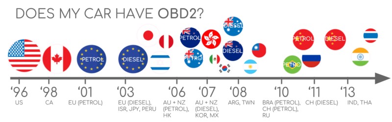
OBD2 Compatibility: Is Your Car Equipped?
The short answer is: Very likely!
The vast majority of modern gasoline and diesel cars, excluding electric vehicles in some respects, are OBD2 compliant and utilize CAN bus for communication. However, for older vehicles, even if you find a 16-pin OBD2 connector, it might not fully support the OBD2 protocol. A key indicator of OBD2 compliance is the vehicle’s market and manufacturing date:
A Look Back: The History of OBD2 and CAN
The story of OBD2 begins in California, driven by the California Air Resources Board (CARB). Starting in 1991, CARB mandated OBD in all new vehicles sold in California for enhanced emission control. This initial system laid the groundwork for the standardized OBD2 we know today.
The Society of Automotive Engineers (SAE) played a crucial role in refining and standardizing OBD. They recommended the OBD2 standard, leading to uniform DTCs and a standardized OBD connector across different vehicle manufacturers (SAE J1962). This standardization was essential for making vehicle diagnostics more accessible and efficient.
The OBD2 standard was gradually implemented worldwide:
- 1996: OBD2 became mandatory in the USA for cars and light trucks.
- 2001: The European Union mandated OBD2 for gasoline cars.
- 2003: OBD2 compliance was extended to diesel cars in the EU (known as EOBD).
- 2005: OBD2 was required in the US for medium-duty vehicles.
- 2008: A significant shift occurred as the US mandated ISO 15765-4 (CAN) as the foundation for OBD2 communication. This marked the widespread adoption of CAN bus within OBD2 systems.
- 2010: OBD2 requirements expanded to heavy-duty vehicles in the US.
The Evolving Future of OBD2: Trends and Challenges
OBD2 is firmly established, but its future is dynamic. Let’s examine key trends shaping its evolution:
Originally, OBD2 was legislated primarily for emissions monitoring and testing. Interestingly, this has led to a situation where electric vehicles (EVs) aren’t strictly required to implement OBD2 in the traditional sense. In practice, many modern EVs deviate from standard OBD2 requests. Instead, they often use OEM-specific UDS (Unified Diagnostic Services) communication protocols. This makes accessing data from EVs more challenging, often requiring reverse engineering to decode proprietary communication – as seen in case studies for electric cars like Tesla, Hyundai/Kia, Nissan, and VW/Skoda EVs.
Recognizing the limitations of traditional OBD2 in terms of data richness and underlying communication protocols, modern alternatives have emerged. These include WWH-OBD (World Wide Harmonized OBD) and OBDonUDS (OBD on UDS). Both are designed to improve OBD communication by utilizing the more versatile UDS protocol as a foundation. For a deeper dive into these protocols, explore our introduction to UDS.
In an increasingly connected world, traditional OBD2 emission checks can seem outdated. Manual inspections are time-consuming and costly.
The proposed solution? OBD3 – integrating telematics into all vehicles.
OBD3 envisions adding a small radio transponder (similar to those used for toll roads) to every car. This would allow for wireless transmission of the car’s vehicle identification number (VIN) and DTCs to a central server for automated monitoring.
Many current devices already facilitate CAN or OBD2 data transfer via WiFi or cellular networks – for example, the CANedge2 WiFi CAN logger and the CANedge3 3G/4G CAN logger.
While offering convenience and cost savings, OBD3 raises political and privacy concerns related to increased vehicle surveillance.
The original purpose of OBD2 was for in-shop emission diagnostics.
However, OBD2 is now widely used by third parties to access real-time vehicle data via OBD2 dongles, CAN loggers and similar tools. This trend is facing pushback from the German car industry, as highlighted in a report by eenewsautomotive.com:
OBD was designed for car servicing in repair shops, not to enable a third-party data-driven economy via this interface.“
– Christoph Grote, SVP Electronics, BMW (2017)
The automotive industry is considering “turning off” OBD2 functionality during normal driving, centralizing data collection within manufacturer-controlled servers. This would give manufacturers control over ‘automotive big data’.
Arguments for this shift include enhanced security (reducing car hacking risks). However, many perceive this as a commercially motivated move. Whether this becomes a widespread practice remains to be seen, but it has the potential to significantly disrupt the market for third-party OBD2 services.
Enhance Your CAN Bus Expertise with Our Ultimate Guide
Ready to become a CAN bus expert?
Access our 12 ‘simple intros’ in a comprehensive 160+ page PDF:
Download now
Understanding OBD2 Standards and CAN Bus Integration
On-board diagnostics, or OBD2, is a higher-layer protocol – essentially a language for vehicle communication. CAN bus, on the other hand, is the communication method – the physical network, like a phone line. This makes OBD2 comparable to other CAN-based higher-layer protocols such as J1939, CANopen, and NMEA 2000.
OBD2 standards define specifications for the OBD2 connector, the lower-layer protocols used for communication, OBD2 Parameter IDs (PIDs), and much more. These standards ensure interoperability and consistent diagnostic access across different vehicle makes and models.
We can visualize these standards using the 7-layer OSI model, a conceptual framework for network protocols. In the following sections, we’ll focus on the most critical OBD2 standards within this model.
Notice in the OSI model overview that both SAE (Society of Automotive Engineers) and ISO (International Organization for Standardization) standards cover several layers. This reflects the development of OBD standards in both the USA (SAE) and Europe (ISO). Many of these standards are technically very similar, such as SAE J1979 and ISO 15031-5, or SAE J1962 and ISO 15031-3.
The OBD2 Connector: SAE J1962 Standard
The 16-pin OBD2 connector provides a standardized and easily accessible interface for retrieving vehicle data. It’s formally defined by the SAE J1962 / ISO 15031-3 standard. This standardization is a cornerstone of OBD2’s widespread usability.
The illustration shows a typical Type A OBD2 pin connector (also known as the Data Link Connector, or DLC).
Key features of the OBD2 connector include:
- Its location is generally near the steering wheel, although it may be somewhat hidden depending on the vehicle.
- Pin 16 provides battery power, often remaining active even when the ignition is off, allowing for diagnostics without the engine running.
- The specific OBD2 pinout configuration depends on the communication protocol used by the vehicle.
- CAN bus is the most prevalent lower-layer protocol, meaning pins 6 (CAN-H) and 14 (CAN-L) are typically connected for CAN communication.
OBD2 Connector Types: A vs. B
You might encounter both Type A and Type B OBD2 connectors in practice. Type A is commonly found in passenger cars and light-duty vehicles, while Type B is more prevalent in medium and heavy-duty vehicles.
As illustrated, both types share a similar OBD2 pinout for data communication, but they differ primarily in their power supply output. Type A typically provides 12V power, suitable for cars, while Type B delivers 24V, appropriate for trucks and buses. Baud rates can also vary, with cars typically using 500 Kbps CAN, while heavy-duty vehicles often use 250 Kbps (though 500 Kbps is becoming more common).
A key physical difference helps distinguish between the two: the Type B OBD2 connector has an interrupted groove in the center. This means a Type B OBD2 adapter cable will be compatible with both Type A and Type B sockets, whereas a Type A adapter will only fit into a Type A socket.
OBD2 and CAN Bus: ISO 15765-4 – Diagnostics over CAN (DoCAN)
Since 2008, CAN bus has been the mandated lower-layer protocol for OBD2 in all vehicles sold in the US, as per the ISO 15765 standard. This standardization on CAN bus significantly simplified and unified vehicle diagnostics.
ISO 15765-4, also known as Diagnostics over CAN or DoCAN, outlines a set of constraints and specifications applied to the CAN standard (ISO 11898) specifically for OBD2 communication.
It standardizes the CAN interface for diagnostic equipment, focusing on the physical layer, data link layer, and network layer:
- The CAN bus bit rate must be either 250 Kbps or 500 Kbps. These are the standard speeds for OBD2 CAN communication.
- CAN IDs can be 11-bit (standard) or 29-bit (extended). Both formats are supported within OBD2 CAN.
- Specific CAN IDs are reserved for OBD requests and responses, ensuring proper communication flow.
- The diagnostic CAN frame data length is fixed at 8 bytes. This is the standard CAN data payload size.
- The OBD2 adapter cable must be a maximum of 5 meters in length to maintain signal integrity.
OBD2 CAN Identifiers: 11-bit and 29-bit
All OBD2 communication, when using CAN, relies on a request-response message structure. A diagnostic tool sends a request, and the vehicle’s ECU responds with the requested data.
In most passenger cars, 11-bit CAN IDs are used for OBD2 communication. The ‘Functional Addressing’ ID, 0x7DF, is commonly used to send a request to all OBD2-compliant ECUs, asking if they have data related to the requested parameter (as defined in ISO 15765-4). ‘Physical Addressing’ requests, using CAN IDs from 0x7E0 to 0x7E7, are less common and target specific ECUs directly.
ECUs respond using 11-bit IDs in the range of 0x7E8 to 0x7EF. The most frequent response ID is 0x7E8 (ECM, Engine Control Module), followed by 0x7E9 (TCM, Transmission Control Module).
In certain vehicles, particularly vans and light, medium, and heavy-duty vehicles, OBD2 communication might utilize extended 29-bit CAN identifiers instead of the standard 11-bit IDs.
In 29-bit CAN, the ‘Functional Addressing’ CAN ID is 0x18DB33F1.
Responses in 29-bit CAN OBD2 typically use CAN IDs ranging from 0x18DAF100 to 0x18DAF1FF (common examples include 18DAF110 and 18DAF11E). These response IDs are sometimes also represented in the ‘J1939 PGN’ format. Specifically, PGN 0xDA00 (55808) is designated in the J1939-71 standard as ‘Reserved for ISO 15765-2’, indicating its use for OBD2 CAN communication within the J1939 framework.
OBD2 CAN vs. OEM-Specific CAN Protocols
It’s crucial to understand that your vehicle’s Electronic Control Units (ECUs) operate using OEM-proprietary CAN protocols for their core functions, independent of OBD2. Each vehicle manufacturer (OEM) designs and implements their own unique CAN protocols. These protocols are often specific to the vehicle brand, model, and year. Without OEM documentation, interpreting this proprietary CAN data is generally not possible unless you undertake reverse engineering.
When you connect a CAN bus data logger to your vehicle’s OBD2 connector, you might observe OEM-specific CAN data alongside OBD2 communication. This OEM data is often broadcast at high rates (1000-2000 frames/second). However, many newer vehicles incorporate a ‘gateway’ module that restricts access to this raw CAN data through the OBD2 port, allowing only standardized OBD2 communication.
In essence, think of OBD2 as a separate, higher-level protocol that operates in parallel with the OEM’s primary, proprietary CAN communication network. OBD2 provides a standardized window into vehicle diagnostics and emissions-related data, while the OEM protocol manages the vehicle’s core operations.
Bit Rate and CAN ID Validation for OBD2 CAN
As mentioned, OBD2 CAN communication can use two different bit rates (250 Kbps, 500 Kbps) and two CAN ID lengths (11-bit, 29-bit). This results in four potential combinations for an OBD2 CAN connection. In modern cars, 500 Kbps and 11-bit IDs are the most common, but diagnostic tools should systematically verify these parameters to ensure proper communication.
ISO 15765-4 provides a recommended initialization sequence to automatically determine the correct combination. This process leverages the fact that OBD2-compliant vehicles must respond to a specific mandatory OBD2 request (we’ll discuss OBD2 PIDs shortly) and that transmitting data at an incorrect bit rate will generate CAN error frames, indicating a mismatch.
More recent versions of ISO 15765-4 account for vehicles that may support OBD communication via OBDonUDS (OBD on Unified Diagnostic Services) instead of the more traditional OBDonEDS (OBD on Emission Diagnostic Service). This article primarily focuses on OBD2/OBDonEDS (defined by ISO 15031-5/SAE J1979) as it’s the more common implementation in non-electric vehicles today. WWH-OBD/OBDonUDS (defined by ISO 14229, ISO 27145-3/SAE J1979-2) is primarily used in EU trucks and buses.
To differentiate between OBDonEDS and OBDonUDS, diagnostic tools can send additional request messages, specifically UDS requests with 11-bit/29-bit functional address IDs for service 0x22 and data identifier (DID) 0xF810 (protocol identification). Vehicles supporting OBDonUDS should have ECUs that respond to this DID.
In practice, OBDonEDS (also known as OBD2, SAE OBD, EOBD, or ISO OBD) is the dominant standard in most non-EV cars today, while WWH-OBD is mainly found in European trucks and buses.
Legacy OBD2 Protocols: Beyond CAN
While CAN bus (ISO 15765) is the dominant lower-layer protocol for OBD2 today, especially in vehicles manufactured after 2008, older vehicles may utilize one of four other protocols. Understanding these legacy protocols can be helpful when working with older cars. The OBD2 connector pinout itself can sometimes provide clues about the protocol in use.
The five lower-layer OBD2 protocols are:
- ISO 15765 (CAN bus): Mandatory in US cars since 2008 and now the most common protocol globally.
- ISO 14230-4 (KWP2000): Keyword Protocol 2000, common in 2003+ vehicles, particularly in Asia.
- ISO 9141-2: Used in European, Chrysler, and Asian vehicles from around 2000-2004.
- SAE J1850 (VPW – Variable Pulse Width Modulation): Primarily used in older General Motors (GM) vehicles.
- SAE J1850 (PWM – Pulse Width Modulation): Primarily used in older Ford vehicles.
ISO-TP: Transporting OBD2 Messages over CAN [ISO 15765-2]
All OBD2 data transmitted over CAN bus uses a transport protocol called ISO-TP (ISO 15765-2). This protocol is essential because it allows for the transmission of data payloads larger than the 8-byte limit of a standard CAN frame. This is crucial for OBD2 functions like retrieving the Vehicle Identification Number (VIN) or Diagnostic Trouble Codes (DTCs), which often require more than 8 bytes of data. ISO 15765-2 handles data segmentation, flow control, and reassembly to manage these larger messages. For more details, see our introduction to UDS, as UDS also utilizes ISO-TP.
However, much of the time, OBD2 data fits within a single CAN frame. In these cases, ISO 15765-2 specifies the use of ‘Single Frame’ (SF) messages. In a Single Frame, the first data byte (the PCI field – Protocol Control Information) indicates the payload length (excluding padding). This leaves 7 bytes within the CAN frame for the actual OBD2 communication.
Decoding the OBD2 Diagnostic Message [SAE J1979, ISO 15031-5]
To understand how OBD2 works over CAN, let’s examine a simplified ‘Single Frame’ OBD2 CAN message. An OBD2 message consists of a CAN identifier, a data length indicator (PCI field), and the actual data payload. The data payload itself is structured into components: Mode, Parameter ID (PID), and data bytes.
Example: OBD2 Request and Response Sequence
Before we delve into the specifics of each part of the OBD2 message, let’s look at a practical example: requesting ‘Vehicle Speed’.
In this scenario, an external diagnostic tool sends a request message to the vehicle. This message uses CAN ID 0x7DF and contains 2 payload bytes: Mode 0x01 and PID 0x0D. The vehicle’s ECU responds with a message using CAN ID 0x7E8 and 3 payload bytes. The fourth byte in the response, 0x32 (which is 50 in decimal), represents the Vehicle Speed value.
By consulting the OBD2 PID specifications for PID 0x0D, we can determine the decoding rules and convert the raw data into a physical value, in this case, 50 km/h.
Next, we’ll explore OBD2 modes and PIDs in more detail.
The 10 Standard OBD2 Services (Modes)
OBD2 defines 10 diagnostic services, often referred to as modes. Each mode serves a specific purpose for accessing diagnostic information. Mode 0x01, for instance, is used to retrieve current, real-time data parameters. Other modes are used to read and clear Diagnostic Trouble Codes (DTCs), access freeze frame data (snapshots of data when a DTC was set), and perform other diagnostic functions.
Vehicles are not required to support all 10 OBD2 modes. Furthermore, manufacturers may implement additional, non-standard modes beyond the ten defined in the OBD2 specifications (these are known as OEM-specific OBD2 modes).
Within OBD2 messages, the mode is indicated in the second byte of the data payload. In a request message, the mode is included directly (e.g., 0x01 for Mode 1). In a response message, 0x40 is added to the requested mode (e.g., a response to Mode 0x01 will have a mode byte of 0x41).
OBD2 Parameter IDs (PIDs)
Within each OBD2 mode, Parameter IDs (PIDs) are used to specify the particular data being requested or provided.
For example, Mode 0x01 (Show current data) includes approximately 200 standardized PIDs. These PIDs represent real-time data points such as vehicle speed, engine RPM, coolant temperature, and fuel level. However, a vehicle doesn’t have to support all PIDs within a given mode. In reality, most vehicles only support a subset of the standardized PIDs.
One PID holds special significance:
If an emissions-related ECU supports any OBD2 services, it must support Mode 0x01 PID 0x00. When this PID is requested, the vehicle’s ECU responds to indicate which PIDs within the range 0x01-0x20 it supports. This makes PID 0x00 a fundamental ‘OBD2 compatibility test’. Similarly, PIDs 0x20, 0x40, 0x60, 0x80, 0xA0, and 0xC0 are used to determine support for subsequent ranges of Mode 0x01 PIDs.
Practical Tip: OBD2 PID Overview Tool
The appendices of SAE J1979 and ISO 15031-5 contain crucial scaling information for standard OBD2 PIDs. This information allows you to convert the raw data bytes into meaningful physical values.
For quick lookup of Mode 0x01 PIDs, our OBD2 PID overview tool is a valuable resource. It helps you construct OBD2 request frames and dynamically decode OBD2 responses, streamlining your diagnostic work.
OBD2 PID overview tool
Hands-on: Logging and Decoding OBD2 CAN Data
Let’s walk through a practical example of logging OBD2 data using a CANedge CAN bus data logger.
The CANedge is configurable to transmit custom CAN frames, making it ideal for OBD2 data logging.
Once configured, you can easily connect the CANedge to your vehicle using our OBD2-DB9 adapter cable.
Test successful CAN frame transmission at 500 Kbps (or 250 Kbps)
Review ‘Supported PIDs’ responses using asammdf software
Step 1: Validate Bit Rate, CAN IDs, and Supported PIDs
As discussed earlier, ISO 15765-4 outlines a procedure to determine the correct bit rate and CAN IDs for OBD2 communication in a specific vehicle. You can perform these validation steps using the CANedge as follows (refer to the CANedge Intro for detailed instructions):
- Bit Rate Test: Send a CAN frame at 500 Kbps and check if it transmits successfully. If not, try 250 Kbps.
- Bit Rate Confirmation: Use the identified bit rate for all subsequent OBD2 communication.
- Supported PIDs Discovery: Send multiple ‘Supported PIDs’ requests (Mode 0x01, PID 0x00, and subsequent range PIDs) and analyze the responses.
- CAN ID Determination: Based on the response CAN IDs, determine if the vehicle uses 11-bit or 29-bit CAN IDs for OBD2.
- PID Support List: Analyze the response data to identify the specific PIDs supported by the vehicle.
We provide pre-configured CANedge configurations to simplify these initial tests.
Most non-electric vehicles manufactured after 2008 typically support 40-80 PIDs using a 500 Kbps bit rate, 11-bit CAN IDs, and the OBD2/OBDonEDS protocol.
As shown in the asammdf GUI screenshot, you may observe multiple responses to a single OBD2 request, particularly when using the functional address ID 0x7DF. This is because this ID polls all OBD2-compliant ECUs. Since all OB