Understanding your car’s On-Board Diagnostics (OBD) system is crucial for modern vehicle maintenance and repair. For older vehicles, particularly those transitioning from OBD1 to the more advanced OBD2, knowing the intricacies of wiring, especially the distributor wiring, becomes essential. This guide will delve into the world of OBD systems, focusing on the critical aspects of distributor wiring when considering an OBD1 to OBD2 conversion.
Decoding OBD-I: The Original Diagnostic System
OBD-I, the first generation of on-board diagnostics, was introduced in the early days of automotive computerization. While a significant step forward from purely mechanical systems, OBD-I was far less standardized and comprehensive than its successor.
Key characteristics of OBD-I include:
- Manufacturer-Specific: OBD-I systems were largely manufacturer-dependent. This meant diagnostic connectors, communication protocols, and the data available varied significantly between car brands and even models within the same brand.
- Limited Diagnostic Capability: OBD-I primarily focused on emissions-related components. Diagnostic trouble codes (DTCs) were often generic and less detailed, making pinpointing the exact issue challenging.
- Basic Connector Types: OBD-I connectors were not standardized. You might find various shapes and pin configurations depending on the vehicle’s make and year.
- Manual Code Retrieval: Accessing diagnostic codes in OBD-I often required specific procedures, like counting check engine light flashes or using proprietary scan tools.
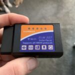
An example of an OBD1 connector, highlighting the non-standardized nature of first-generation diagnostic ports.
Embracing OBD-II: The Standard in Automotive Diagnostics
OBD-II marked a significant leap forward, becoming mandatory in the United States for all cars manufactured after 1996. This second generation brought standardization, enhanced diagnostic capabilities, and a wealth of information accessible to mechanics and car owners alike.
Key improvements with OBD-II:
- Standardization: OBD-II mandated a standardized J1962 16-pin diagnostic connector, regardless of vehicle make or model. This universal connector allows any compliant scan tool to interface with any OBD-II vehicle.
- Enhanced Diagnostics: OBD-II expanded diagnostic coverage beyond emissions to include powertrain, chassis, and body systems. It provides more detailed and specific DTCs, aiding in accurate problem identification.
- Comprehensive Data Parameters (PIDs): OBD-II systems offer access to a wide range of live data parameters, such as engine speed (RPM), coolant temperature, oxygen sensor readings, and much more. This real-time data is invaluable for troubleshooting and performance monitoring.
- Standardized Protocols: OBD-II utilizes standardized communication protocols like CAN (Controller Area Network), ISO 9141, and PWM (Pulse Width Modulation), ensuring consistent communication between the vehicle and diagnostic tools.
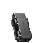
A standard OBD2 connector, showcasing the 16-pin layout that ensures compatibility across different vehicle makes and models.
Why Consider an OBD1 to OBD2 Conversion?
For owners of older vehicles originally equipped with OBD-I, upgrading to OBD-II can offer several advantages:
- Improved Diagnostic Accuracy: OBD-II’s enhanced diagnostic capabilities and detailed DTCs lead to more accurate and faster troubleshooting, saving time and money on repairs.
- Access to Modern Scan Tools: OBD-II compatibility opens the door to a wide array of affordable and user-friendly OBD-II scan tools available on the market. These tools provide more data and features than older OBD-I scanners.
- Enhanced Engine Management: In some conversion scenarios, upgrading to OBD-II may involve using a more modern engine control unit (ECU) that offers better engine management and tuning potential.
- Future-Proofing: As diagnostic technology advances, OBD-II remains the industry standard, ensuring better compatibility with future tools and systems.
The Role of Distributor Wiring in OBD1 to OBD2 Conversions
When undertaking an OBD1 to OBD2 conversion, particularly if it involves changing the ECU or engine management system, distributor wiring diagrams become crucial. The distributor plays a vital role in ignition timing, and its wiring must be correctly integrated with the new OBD2 system and ECU.
Here’s why distributor wiring diagrams are essential:
- Pinout Identification: Wiring diagrams clearly illustrate the pinout of both the OBD1 and OBD2 distributors (if applicable, as some OBD2 systems are distributorless). This is critical for understanding which wire corresponds to which function (e.g., ignition signal, ground, power).
- Wiring Compatibility: OBD1 and OBD2 systems often use different wiring configurations. A wiring diagram helps identify incompatible wires and determine how to properly adapt or rewire the distributor for the new system.
- Avoiding Electrical Damage: Incorrect wiring can lead to short circuits, blown fuses, or damage to the ECU and distributor. Accurate wiring diagrams minimize the risk of electrical issues during the conversion process.
- Ensuring Proper Ignition Timing: The distributor’s wiring is directly linked to ignition timing. Incorrect wiring can result in improper timing, leading to poor engine performance, misfires, and potential engine damage.
A simplified example of a distributor wiring diagram, illustrating the connections between the distributor, ECU, and other engine components. Actual diagrams vary based on vehicle and system.
Note: It’s important to understand that not all OBD1 to OBD2 conversions require distributor rewiring. Some conversions might involve adapter harnesses or ECUs that are designed to be plug-and-play with the existing distributor wiring. However, for more complex conversions or when adapting components from different vehicles, wiring diagrams are indispensable.
Finding and Utilizing OBD1 to OBD2 Distributor Wiring Diagrams
Locating accurate wiring diagrams is paramount for a successful OBD1 to OBD2 conversion. Here are reliable sources:
- Vehicle-Specific Repair Manuals: Factory service manuals or reputable aftermarket repair manuals (like Haynes or Chilton) often contain detailed wiring diagrams for specific vehicle makes and models.
- Online Wiring Diagram Databases: Several online services and forums specialize in providing automotive wiring diagrams. Some may require a subscription, while others offer diagrams for free or for a small fee.
- Automotive Forums and Communities: Online forums dedicated to specific car models or engine swaps can be valuable resources. Experienced members may have diagrams or be able to provide guidance.
- Professional Diagnostic Software: Some professional-grade diagnostic software includes built-in wiring diagram databases.
When using wiring diagrams:
- Verify Accuracy: Always double-check that the wiring diagram you are using is for the correct vehicle year, make, model, and engine type.
- Understand Symbols and Conventions: Familiarize yourself with the symbols and conventions used in wiring diagrams to correctly interpret the information.
- Work Methodically: Follow the diagram step-by-step, carefully tracing wires and making connections as indicated.
- Test and Verify: After wiring, thoroughly test all connections and use an OBD-II scan tool to ensure proper system functionality and check for any DTCs.
Conclusion: Wiring is Key to a Successful OBD Upgrade
Upgrading from OBD1 to OBD2 can significantly enhance your vehicle’s diagnostic capabilities and engine management. While the process can range from simple to complex, understanding the distributor wiring and utilizing accurate wiring diagrams is often a critical aspect, especially when modifying or adapting engine control systems. By carefully planning, using the correct diagrams, and working methodically, you can successfully navigate the wiring challenges of an OBD1 to OBD2 conversion and reap the benefits of modern automotive diagnostics.