Looking for a detailed understanding of the Iso 15765 Can Obd2 Protocol?
This in-depth guide provides a comprehensive explanation of the ISO 15765 standard as it relates to OBD2 and CAN bus communication in modern vehicles. We’ll delve into the intricacies of this protocol, exploring its significance in automotive diagnostics, data retrieval, and how it underpins the communication within your car’s network.
This article goes beyond a basic introduction, offering a deep dive into the practical aspects of the ISO 15765 CAN OBD2 protocol, including its history, technical specifications, and real-world applications. Understand why this protocol is crucial for anyone involved in vehicle repair, modification, or data analysis.
You can also enhance your knowledge by exploring our introductory video on OBD2 or downloading our detailed PDF guide on CAN bus.
Article Contents:
Author: Martin Falch (Expert in Automotive Diagnostics) – Updated for 2025
Download as PDF
Decoding OBD2: The Role of ISO 15765 and CAN Bus
OBD2, or On-Board Diagnostics II, is an essential system integrated into modern vehicles. It acts as the car’s internal health monitor, capable of self-diagnosing issues and providing valuable data. This standardized protocol enables access to Diagnostic Trouble Codes (DTCs) and real-time vehicle parameters through the OBD2 connector.
You’re likely familiar with OBD2 through the check engine light on your dashboard. This light signals a problem detected by the OBD2 system. When you take your car to a mechanic, they utilize an OBD2 scanner to pinpoint the issue.
The mechanic connects the OBD2 scanner to the 16-pin OBD2 connector, usually located near the steering wheel. This tool sends ‘OBD2 requests’ to the vehicle’s electronic control units (ECUs). The vehicle responds with ‘OBD2 responses’ containing data such as speed, fuel level, or DTCs. This streamlined communication significantly speeds up troubleshooting and repair processes.
Image alt text: OBD2 system depicted with a scan tool connected to a car’s OBD2 port, highlighting the Malfunction Indicator Light (MIL) or check engine light.
OBD2 Compatibility: Is Your Car Equipped?
The likelihood is high that your car supports OBD2!
Nearly all contemporary non-electric vehicles are OBD2 compliant, and a majority utilize CAN bus for communication. However, for older vehicles, the presence of a 16-pin OBD2 connector doesn’t guarantee OBD2 support. Compliance depends on the vehicle’s origin and manufacturing date:
Image alt text: Chart illustrating OBD2 compliance timelines for vehicles based on region (EU, US) and vehicle type, indicating dates from which OBD2 became mandatory.
A Look at OBD2 History and the Rise of ISO 15765
The origins of OBD2 trace back to California. The California Air Resources Board (CARB) mandated OBD in all new vehicles from 1991 onwards to monitor and control emissions.
The Society of Automotive Engineers (SAE) played a crucial role in standardizing OBD2, recommending the protocol and standardizing DTCs and the OBD connector across different manufacturers through SAE J1962.
The adoption of OBD2 progressed in stages:
- 1996: OBD2 became mandatory in the USA for cars and light trucks.
- 2001: The EU required OBD2 for gasoline cars.
- 2003: The EU extended the requirement to diesel cars (EOBD – European On-Board Diagnostics).
- 2005: OBD2 was mandated in the US for medium-duty vehicles.
- 2008: A pivotal year, US vehicles were required to utilize ISO 15765-4 (CAN) as the foundation for OBD2 communication, solidifying the ISO 15765 CAN OBD2 protocol.
- 2010: OBD2 was finally required for heavy-duty vehicles in the US.
Image alt text: Graphic depicting the historical progression of OBD2 implementation, emphasizing emission control, exhaust standards, and the evolution to EOBD2 and EOBDII.
Image alt text: Timeline visualization of OBD2 history, highlighting key milestones and dates related to its development and mandatory adoption in different regions.
Image alt text: Illustration of the future trends in OBD, including OBD3, remote diagnostics, emissions testing, cloud connectivity, and IoT integration.
The Future of OBD2: Trends and Innovations
OBD2 remains a vital part of vehicle technology, but its future is evolving.
Initially designed for emissions monitoring and testing, legislated OBD2 presents limitations, particularly for electric vehicles (EVs). Modern EVs largely bypass standard OBD2 requests, opting for OEM-specific UDS communication. This makes accessing data from EVs challenging, often requiring reverse engineering to decode proprietary protocols. However, resources are emerging, such as case studies for electric cars including Tesla, Hyundai/Kia, Nissan, and VW/Skoda EVs, which demonstrate progress in accessing EV data.
Recognizing the limitations of current OBD2 implementations in data richness and lower-layer protocols, alternatives like WWH-OBD (World Wide Harmonized OBD) and OBDonUDS (OBD on UDS) have been developed. These aim to improve OBD communication by utilizing the UDS protocol as a base. Further details can be found in our introduction to UDS.
The rise of connected cars highlights the cumbersome nature of traditional OBD2 testing. Manual emission checks are time-consuming and costly.
OBD3 emerges as a potential solution by integrating telematics into vehicles. OBD3 envisions adding a small radio transponder to cars, enabling wireless transmission of the vehicle identification number (VIN) and DTCs to a central server for automated checks.
Devices like the CANedge2 WiFi CAN logger and CANedge3 3G/4G CAN logger already facilitate data transfer via WiFi/cellular networks. While offering convenience and cost savings, OBD3 raises political and privacy concerns related to surveillance.
Originally intended for stationary emission controls, OBD2 is now widely used by third parties for real-time data generation through OBD2 dongles, CAN loggers, etc. However, the German car industry is exploring options to restrict this third-party access, as stated by Christoph Grote, SVP Electronics at BMW in 2017:
“OBD has been designed to service cars in repair shops. In no way has it been intended to allow third parties to build a form of data-driven economy on the access through this interface“
The proposal involves disabling OBD2 functionality during driving and centralizing data collection with manufacturers. This would give manufacturers control over ‘automotive big data’. Arguments for this change center on security, such as reducing car hacking risks, though many perceive it as a commercially motivated strategy, potentially disrupting the market for third-party OBD2 services, as discussed by navixy.com. The future of OBD2 and third-party access remains uncertain.
Image alt text: Visual representation of the future challenge for OBD2 as electric vehicles increasingly restrict data access through the OBD2 connector.
Enhance Your CAN Bus Expertise
Become a CAN bus expert with our comprehensive guide!
Access 12 ‘simple introductions’ in our extensive 160+ page PDF:
Download now
Understanding OBD2 Standards: ISO 15765 and Beyond
On-board diagnostics, OBD2, operates as a higher-layer protocol, essentially a language for communication. CAN (Controller Area Network) is the communication method, analogous to a telephone line. This positions OBD2 alongside other CAN-based higher-layer protocols like J1939, CANopen, and NMEA 2000.
Specifically, OBD2 standards define the OBD2 connector, lower-layer protocols, OBD2 Parameter IDs (PIDs), and more.
These standards can be mapped to the 7-layer OSI model. The following sections will focus on the most critical standards.
In the OSI model context, you’ll notice that both SAE and ISO standards cover multiple layers. This reflects the standardization efforts for OBD in the USA (SAE) and EU (ISO). Many standards are technically very similar, such as SAE J1979 and ISO 15031-5, and SAE J1962 and ISO 15031-3. The ISO 15765 series is particularly important as it defines OBD2 implementation over CAN bus, known as ISO 15765 CAN OBD2 protocol.
Image alt text: OSI 7-layer model diagram illustrating the relationship between OBD2, CAN Bus, ISO 15765, and ISO 11898 standards, showing their respective layers in the communication stack.
Image alt text: Detailed pinout diagram of a Type A female OBD2 connector socket (Data Link Connector DLC), labeling each pin and its function.
The OBD2 Connector: SAE J1962 and ISO 15031-3
The 16-pin OBD2 connector provides straightforward access to vehicle data and is detailed in SAE J1962 / ISO 15031-3 standards. This standard ensures interoperability of diagnostic tools across different vehicle makes and models.
The illustration shows a Type A OBD2 pin connector (Data Link Connector, DLC).
Key features of the OBD2 connector:
- Typically located near the steering wheel, although it may be concealed.
- Pin 16 provides battery power, often active even when the ignition is off, allowing for diagnostics without the engine running.
- The OBD2 pinout configuration varies depending on the communication protocol used.
- CAN bus is the most prevalent lower-layer protocol, meaning pins 6 (CAN-H) and 14 (CAN-L) are commonly connected for CAN communication as defined by ISO 15765 CAN OBD2 protocol.
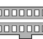
OBD2 Connector Types: A vs. B
You might encounter both Type A and Type B OBD2 connectors. Type A is standard in cars, while Type B is more common in medium and heavy-duty vehicles.
While both types share similar OBD2 pinouts, they differ in power supply outputs: 12V for Type A and 24V for Type B. Baud rates can also vary, with cars typically using 500K and heavy-duty vehicles often using 250K (with increasing support for 500K).
Visually, the Type B OBD2 connector has a distinguishing interrupted groove in the center. A Type B OBD2 adapter cable is compatible with both Type A and B sockets, whereas a Type A adapter will not fit into a Type B socket.
Image alt text: Comparison diagram of OBD2 Connector Type A and Type B, highlighting differences in grooves, voltage (12V vs 24V), and typical vehicle applications (car/van vs. truck).
Image alt text: Diagram illustrating the relationship between OBD2 and CAN bus, emphasizing ISO 15765 as the standard defining OBD2 over CAN.
ISO 15765-4: OBD2 and CAN Bus Integration
Since 2008, CAN bus, under the ISO 15765-4 standard, has become the mandatory lower-layer protocol for OBD2 in all vehicles sold in the US. This standard is central to the ISO 15765 CAN OBD2 protocol.
ISO 15765-4, also known as Diagnostics over CAN or DoCAN, specifies a set of constraints and guidelines for using CAN (ISO 11898) for diagnostic communication.
Specifically, it standardizes the CAN interface for diagnostic equipment, focusing on the physical, data link, and network layers:
- CAN bus bit-rate must be either 250K or 500K. These rates are chosen to balance speed and reliability in automotive environments.
- CAN IDs can be 11-bit or 29-bit, accommodating both standard and extended CAN addressing schemes.
- Specific CAN IDs are reserved for OBD requests and responses, ensuring proper routing of diagnostic messages.
- The diagnostic CAN frame data length is fixed at 8 bytes, the standard payload size for CAN frames.
- The OBD2 adapter cable is limited to a maximum length of 5 meters to maintain signal integrity.
OBD2 CAN Identifiers: 11-bit and 29-bit Addressing
OBD2 communication over CAN relies on request and response message exchanges.
In most passenger vehicles, 11-bit CAN IDs are used for OBD2 communication. The ‘Functional Addressing’ ID, 0x7DF, is used to broadcast a request to all OBD2-compatible ECUs, asking if they have data to report on the requested parameter (as per ISO 15765-4). ‘Physical Addressing’ requests, using CAN IDs 0x7E0-0x7E7, target specific ECUs but are less frequently used.
ECUs respond using 11-bit IDs in the range 0x7E8-0x7EF. The most common response ID is 0x7E8 (Engine Control Module, ECM), followed by 0x7E9 (Transmission Control Module, TCM).
Some vehicles, particularly vans and light/medium/heavy-duty vehicles, may employ extended 29-bit CAN identifiers for OBD2 communication instead of 11-bit IDs.
In 29-bit CAN, the ‘Functional Addressing’ CAN ID is 0x18DB33F1.
Responses in 29-bit CAN are typically seen with CAN IDs ranging from 0x18DAF100 to 0x18DAF1FF, commonly 0x18DAF110 and 0x18DAF11E. These response IDs are sometimes represented in ‘J1939 PGN’ format. Specifically, PGN 0xDA00 (55808) is marked as ‘Reserved for ISO 15765-2’ in the J1939-71 standard, indicating its use in ISO 15765 CAN OBD2 protocol.
Image alt text: Illustration of OBD2 protocol request and response frames, highlighting the structure of messages and the role of PID (Parameter ID) in data requests.
Image alt text: Diagram contrasting OBD2 and proprietary CAN bus protocols, illustrating that OBD2 is an additional layer on top of OEM-specific CAN data used for vehicle functions.
OBD2 vs. OEM Proprietary CAN Protocols
It’s crucial to understand that vehicle ECUs primarily function using OEM-proprietary CAN protocols, not OBD2. Each OEM develops unique CAN protocols specific to their vehicle brands, models, and years. This OEM-specific CAN data is typically inaccessible to external parties unless reverse engineered.
Connecting a CAN bus data logger to the OBD2 connector might capture OEM-specific CAN data, usually broadcast at 1000-2000 frames/second. However, newer vehicles often have a ‘gateway’ that restricts access to OEM CAN data through the OBD2 port, allowing only OBD2 communication.
Think of OBD2 as an additional higher-layer protocol operating alongside the OEM-specific protocol. The ISO 15765 CAN OBD2 protocol standardizes this additional layer for diagnostics.
Bit-rate and ID Validation in ISO 15765-4
As defined by ISO 15765-4, OBD2 over CAN may use two bit-rates (250K, 500K) and two CAN ID lengths (11-bit, 29-bit), resulting in four possible combinations. Modern cars commonly use 500K and 11-bit IDs, but diagnostic tools should systematically verify these parameters.
ISO 15765-4 provides a recommended initialization sequence to determine the correct combination. This method relies on the fact that OBD2-compliant vehicles must respond to a mandatory OBD2 request (see OBD2 PID section) and that incorrect bit-rates will cause CAN error frames.
Newer versions of ISO 15765-4 account for vehicles supporting OBD communication via OBDonUDS (OBD on Unified Diagnostic Services) instead of OBDonEDS (OBD on Emission Diagnostic Services). This article primarily focuses on OBD2/OBDonEDS (ISO 15031-5/SAE J1979) as opposed to WWH-OBD/OBDonUDS (ISO 14229, ISO 27145-3/SAE J1979-2).
To distinguish between OBDonEDS and OBDonUDS, diagnostic tools can send additional UDS requests with 11-bit/29-bit functional address IDs for service 0x22 and Data Identifier (DID) 0xF810 (protocol identification). Vehicles supporting OBDonUDS must respond to this DID.
OBDonEDS (OBD2, SAE OBD, EOBD, ISO OBD) is prevalent in most non-EV cars today, while WWH-OBD is primarily used in EU trucks and buses. Understanding these distinctions is crucial for correctly implementing ISO 15765 CAN OBD2 protocol.
Image alt text: Flowchart illustrating the OBD2 bit-rate and CAN ID validation process according to ISO 15765-4, outlining steps for automatic detection of correct communication parameters.
Image alt text: Diagram showing the five lower-layer OBD2 protocols: CAN (ISO 15765), KWP2000 (ISO14230-4), SAE J1850 VPW, SAE J1850 PWM, and ISO 9141, highlighting CAN as the dominant protocol today.
Legacy OBD2 Protocols and the Dominance of ISO 15765
While CAN, as defined in ISO 15765, is now the dominant lower-layer protocol for OBD2, especially in vehicles manufactured post-2008, it’s important to recognize the four legacy protocols used in older vehicles. Pinouts can help identify the protocol used in pre-2008 cars:
- ISO 15765 (CAN bus): Mandatory in US cars since 2008 and now the most widely used protocol globally, forming the basis of ISO 15765 CAN OBD2 protocol.
- ISO14230-4 (KWP2000): Keyword Protocol 2000, common in 2003+ vehicles, particularly in Asia.
- ISO 9141-2: Used in EU, Chrysler, and Asian cars from 2000-2004.
- SAE J1850 (VPW): Predominantly used in older GM vehicles.
- SAE J1850 (PWM): Primarily used in older Ford vehicles.
ISO 15765-2: Transporting OBD2 Messages via ISO-TP
All OBD2 data communication over CAN bus relies on ISO-TP (ISO 15765-2), a transport protocol enabling transmission of payloads exceeding the 8-byte CAN frame limit. This is essential for OBD2 functions like retrieving the Vehicle Identification Number (VIN) or Diagnostic Trouble Codes (DTCs). ISO 15765-2 handles segmentation, flow control, and reassembly of these larger messages. More details are available in our introduction to UDS.
However, much OBD2 data fits within a single CAN frame. In these cases, ISO 15765-2 specifies the use of ‘Single Frame’ (SF) messages. The first data byte (PCI field) indicates the payload length (excluding padding), leaving 7 bytes for OBD2-specific communication. This efficient use of single frames is a key aspect of ISO 15765 CAN OBD2 protocol.
Image alt text: Diagram illustrating ISO-TP (ISO 15765-2) frame types used in OBD2 communication, including Single Frame, First Frame, Consecutive Frame, and Flow Control Frame.
SAE J1979 and ISO 15031-5: The OBD2 Diagnostic Message
To understand OBD2 over CAN, consider a raw ‘Single Frame’ OBD2 CAN message. Simplified, an OBD2 message comprises an identifier, data length (PCI field), and data. The data field is further structured into Mode, Parameter ID (PID), and data bytes. These components are central to how ISO 15765 CAN OBD2 protocol operates at the message level.
Image alt text: Breakdown of the OBD2 message structure, explaining components like Mode, PID (Parameter ID), and data bytes within a raw OBD2 frame.
OBD2 Request/Response Example: Vehicle Speed
Let’s examine a request/response example for ‘Vehicle Speed’.
An external tool sends a request message to the car with CAN ID 0x7DF and 2 payload bytes: Mode 0x01 and PID 0x0D. The car responds via CAN ID 0x7E8 with 3 payload bytes, including the Vehicle Speed value in the 4th byte, 0x32 (decimal 50).
Referring to OBD2 PID 0x0D decoding rules, we find that the physical value is 50 km/h. This simple exchange demonstrates the fundamental request-response mechanism of ISO 15765 CAN OBD2 protocol.
Image alt text: Example of OBD2 request (CAN ID 7DF) and response (CAN ID 7E8) messages for Vehicle Speed, showing the data exchange process.
Image alt text: Detailed example of OBD2 PID 0D (Vehicle Speed), illustrating the request, response, and data byte interpretation to derive the speed value.
Image alt text: Overview of the 10 OBD2 diagnostic services (modes), including descriptions of modes like current data, freeze frame data, clearing DTCs, and their functions.
OBD2 Services (Modes)
OBD2 defines 10 diagnostic services, also known as modes. Mode 0x01 is used to retrieve current real-time data, while other modes are for accessing or clearing Diagnostic Trouble Codes (DTCs), or retrieving freeze frame data. These modes are standardized across vehicles to ensure consistent diagnostic procedures under ISO 15765 CAN OBD2 protocol.
Vehicles are not required to support all OBD2 modes, and may also implement OEM-specific modes beyond the 10 standardized ones.
In OBD2 messages, the mode is located in the 2nd byte. In a request, the mode is included directly (e.g., 0x01). In a response, 0x40 is added to the mode value (e.g., resulting in 0x41).
OBD2 Parameter IDs (PIDs) and ISO 15031-5/SAE J1979
Within each OBD2 mode, Parameter IDs (PIDs) specify the data being requested.
For example, mode 0x01 contains approximately 200 standardized PIDs for real-time data such as speed, RPM, and fuel level. However, vehicles don’t necessarily support all PIDs within a mode; in practice, most vehicles support only a subset. The standardization of PIDs is a key feature of ISO 15765 CAN OBD2 protocol, ensuring consistent data access across different vehicle manufacturers.
One PID, PID 0x00 in mode 0x01, is particularly significant.
If an emissions-related ECU supports any OBD2 services, it must support mode 0x01 PID 0x00. Responding to this PID, the vehicle ECU indicates its support for PIDs 0x01-0x20. This makes PID 0x00 a fundamental ‘OBD2 compatibility test’. PIDs 0x20, 0x40, 0x60, … , 0xC0 are then used to determine support for subsequent ranges of mode 0x01 PIDs.
Image alt text: Re-display of the OBD2 protocol request and response frame illustration, emphasizing the role of PID in specifying data parameters within OBD2 messages.
Image alt text: Screenshot of an OBD2 PID overview tool, showing a user interface for selecting and viewing details of OBD2 PIDs under service 01, facilitating PID lookup and understanding.
OBD2 PID Overview Tool: A Practical Resource
Appendixes in SAE J1979 and ISO 15031-5 contain scaling information for standard OBD2 PIDs, enabling the conversion of raw data into physical values (as explained in our CAN bus introduction). These standards are the definitive sources for understanding ISO 15765 CAN OBD2 protocol data interpretation.
For quick lookup of mode 0x01 PIDs, our OBD2 PID overview tool is a helpful resource. It assists in constructing OBD2 request frames and dynamically decoding OBD2 responses.
OBD2 PID overview tool
Practical Guide: Logging and Decoding OBD2 Data with ISO 15765 CAN OBD2 Protocol
This section provides a practical example of logging OBD2 data using the CANedge CAN bus data logger. The CANedge’s configurability makes it ideal for interacting with ISO 15765 CAN OBD2 protocol.
The CANedge allows custom CAN frame transmission, making it suitable for OBD2 logging.
Connect the CANedge to your vehicle using our OBD2-DB9 adapter cable for easy setup.
Image alt text: Diagram showing an OBD2 PID data logger setup, illustrating the CANedge connected to a vehicle’s OBD2 port and sending request frames (7DF) and receiving responses (7E8).
You can send a CAN frame at e.g. 500K, then check if it is successfully sent
The responses to ‘Supported PIDs’ can be reviewed in asammdf
Image alt text: Screenshot of an OBD2 PID lookup tool displaying decoded ‘Supported PIDs’ results, enabling users to interpret the vehicle’s response and identify supported PIDs.
Step #1: Testing Bit-rate, IDs, and Supported PIDs according to ISO 15765-4
ISO 15765-4 outlines how to determine the correct bit-rate and IDs for a vehicle. Use CANedge to test this:
- Transmit a CAN frame at 500K and check for success (if unsuccessful, try 250K).
- Use the validated bit-rate for all subsequent communication.
- Send multiple ‘Supported PIDs’ requests and analyze responses.
- Determine 11-bit vs. 29-bit IDs based on response IDs.
- Identify supported PIDs from response data.
We provide plug-and-play configurations for these tests. Most post-2008 non-EV cars support 40-80 PIDs using 500K bit-rate, 11-bit CAN IDs, and the OBD2/OBDonEDS protocol, all within the framework of ISO 15765 CAN OBD2 protocol.
The asammdf GUI screenshot shows multiple responses to a single OBD request due to the 0x7DF request ID, which polls all ECUs. Since all OBD2/OBDonEDS-compliant ECUs must support service 0x01 PID 0x00, many responses to this PID are common. Subsequent ‘Supported PIDs’ requests receive fewer responses as fewer ECUs support those PIDs. The ECM ECU (0x7E8) often supports all PIDs supported by other ECUs in this example, suggesting that busload can be reduced by directing requests specifically to the ECM using ‘Physical Addressing’ CAN ID 0x7E0 for future communication.
Step #2: Configuring OBD2 PID Requests for Targeted Data Acquisition
Once you know the supported PIDs, bit-rate, and CAN IDs, configure your CANedge transmit list with desired PIDs.
Consider these factors for efficient and reliable OBD2 data logging:
- CAN IDs: Switch to ‘Physical Addressing’ request IDs (e.g., 0x7E0) to avoid redundant responses.
- Spacing: Introduce 300-500 ms intervals between OBD2 requests to prevent ECU overload.
- Battery Drain: Implement triggers to stop transmissions when the vehicle is inactive to conserve battery and prevent ECU ‘wake-up’.
- Filters: Apply filters to record only OBD2 responses if OEM-specific CAN data is also present.
With these configurations, CANedge is ready to log raw OBD2 data according to ISO 15765 CAN OBD2 protocol.
An example list of CANedge OBD2 PID requests
asammdf lets you DBC decode and visualize OBD2 data
Step #3: DBC Decoding of Raw OBD2 Data for Analysis
To analyze and visualize logged data, decode raw OBD2 data into ‘physical values’ (e.g., km/h, °C).
Decoding information is in ISO 15031-5/SAE J1979 (and Wikipedia). We offer a free OBD2 DBC file for easy DBC decoding in most CAN bus software tools. This DBC file is designed to work seamlessly with data logged following ISO 15765 CAN OBD2 protocol.
Decoding OBD2 data is more complex than standard CAN signals because different OBD2 PIDs share the same CAN ID (e.g., 0x7E8). The CAN ID alone isn’t enough to identify the signals in the payload.
Solution: use CAN ID, OBD2 mode, and OBD2 PID to identify signals. This is ‘extended multiplexing’, implementable in DBC files.
CANedge: Your OBD2 Data Logging Solution
The CANedge simplifies OBD2 data recording to an 8-32 GB SD card. Connect to a vehicle to start logging and decode data with free software/APIs and our OBD2 DBC. It’s designed for efficient and reliable data capture under ISO 15765 CAN OBD2 protocol.
OBD2 logger intro
CANedge
Multi-Frame OBD2 Examples and ISO-TP [ISO 15765-2]
Most examples so far are single-frame communication. This section covers multi-frame communication, essential for larger OBD2 data transfers as defined by ISO-TP and ISO 15765 CAN OBD2 protocol.
Multi-frame OBD2 communication requires flow control frames (see our UDS intro). A static flow control frame transmitted ~50 ms after the initial request frame is a common practice, as shown in the CANedge configuration example.
Multi-frame OBD2 responses necessitate CAN software/API tools with ISO-TP support, like CANedge MF4 decoders.
Image alt text: Example of an OBD2 multi-frame request message for Vehicle Identification Number (VIN), demonstrating the structure of multi-frame requests.
Example 1: OBD2 Vehicle Identification Number (VIN) Retrieval
The Vehicle Identification Number (VIN) is crucial for telematics and diagnostics (see our UDS intro). To get the VIN using OBD2, use mode 0x09 and PID 0x02:
The tester tool sends a Single Frame request with PCI field (0x02), service identifier (0x09), and PID (0x02).
The vehicle responds with a First Frame containing PCI, length (0x014 = 20 bytes), mode (0x49), and PID (0x02). Byte 0x01 after the PID is the Number Of Data Items (NODI), here 1. The remaining 17 bytes are the VIN, convertible from HEX to ASCII.
Example 2: OBD2 Multi-PID Request (6x) – Advanced Data Acquisition
External tools can request up to 6 mode 0x01 OBD2 PIDs in a single request frame. The ECU responds with data for supported PIDs (excluding unsupported ones), possibly across multiple frames via ISO-TP. This advanced technique pushes the boundaries of ISO 15765 CAN OBD2 protocol for efficient data retrieval.
This feature allows higher frequency and efficiency data collection, but signal encoding becomes request-specific, complicating generic OBD2 DBC file use. Generally, this method is not recommended for typical use cases. Below is an example trace:
The multi-frame response is similar to the VIN example, but the payload includes requested PIDs and their data. PIDs are often ordered as requested.
DBC decoding becomes challenging due to the request-specific encoding. Generic OBD2 DBC files are less useful. This approach is not recommended for practical data logging unless specialized tools with built-in support are used. Extended multiplexing complexities increase further when sending multiple multi-PID requests, making message identification difficult.
Workarounds involve custom scripts and recording transmit messages to interpret responses based on requests. However, these methods are hard to scale.
Example 3: OBD2 Diagnostic Trouble Codes (DTCs) – Error Diagnosis
Mode 0x03, ‘Show stored Diagnostic Trouble Codes’, retrieves emissions-related DTCs. No PID is in the request. ECUs respond with the number of stored DTCs (possibly 0) and 2 bytes per DTC. Multi-frame responses are needed for more than 2 DTCs. DTC retrieval and interpretation are crucial diagnostic functions within ISO 15765 CAN OBD2 protocol.
The 2-byte DTC value is split into category (first 2 bits) and a 4-digit hexadecimal code. Decoded DTCs can be looked up in OBD2 DTC lookup tools like repairpal.com.
Example: request to an ECU with 6 stored DTCs.
Image alt text: OBD2 DTC decoding example, illustrating how to interpret the 2-byte DTC code to determine category and specific fault code.
OBD2 Data Logging Use Cases: Applications Across Industries
OBD2 data from cars and light trucks has numerous applications:
Image alt text: Illustration of an OBD2 data logger in a car, representing the use case of on-board diagnostics and data acquisition.
Car Data Logging: Fuel Efficiency, Driving Improvement, and More
OBD2 data helps reduce fuel costs, improve driving habits, test prototype parts, and inform insurance models.
obd2 logger
Image alt text: Graphic depicting OBD2 real-time streaming diagnostics via USB, indicating applications in live vehicle monitoring and issue diagnosis.
Real-time Car Diagnostics: Immediate Issue Detection
OBD2 interfaces stream human-readable data in real-time for vehicle diagnostics and issue identification.
obd2 streaming
Image alt text: Representation of OBD2 data logger for predictive maintenance, showing data being transmitted to the cloud for IoT-based vehicle health monitoring.
Predictive Maintenance: Preventing Breakdowns with IoT
IoT OBD2 loggers monitor vehicles in the cloud to predict and prevent breakdowns.
predictive maintenance
Image alt text: Illustration of a black box CAN logger for vehicle data recording, suggesting applications in insurance, warranty, and accident analysis.
Vehicle Black Box Logging: Data for Disputes and Diagnostics
OBD2 loggers serve as ‘black boxes’ for vehicles, providing data for disputes and diagnostics.
can bus blackbox
Do you have an OBD2 data logging use case? Contact us for free consultation!
Contact us
Explore our guides or download the ‘Ultimate Guide’ PDF for more introductions.
Need to log/stream OBD2 data following ISO 15765 CAN OBD2 protocol?
Get your OBD2 data logger today!
Buy now
Contact us
Recommended Resources
OBD2 DATA LOGGER: EASILY LOG & CONVERT OBD2 DATA
CANEDGE2 – PRO CAN IoT LOGGER
CAN BUS INTERFACE: STREAMING OBD2 DATA WITH SAVVYCAN