Navigating the intricacies of automotive diagnostics can be challenging, especially when dealing with older vehicles transitioning to new standards. For Honda owners working on models around 1997, understanding the OBD2 pinout is crucial for effective troubleshooting and ECU data reading. This article delves into the Honda 1997 Obd2 Pinout, providing a comprehensive guide to ensure you can accurately connect your diagnostic tools and interpret the data.
Understanding OBD2 and Honda Diagnostic Systems
The introduction of On-Board Diagnostics II (OBD2) was a significant step towards standardized automotive diagnostics. However, the transition period around 1997 means that some vehicles, including Hondas of this era, can present unique challenges. While OBD2 aimed to standardize the 16-pin Diagnostic Link Connector (DLC), the implementation across different manufacturers and models wasn’t always uniform initially.
For Honda vehicles manufactured around 1997, it’s essential to recognize that you might encounter variations. Some models might be fully compliant with the OBD2 standard, while others could retain elements of the older systems or implement OBD2 in a slightly different way. This is where understanding the specific pinout for your 1997 Honda becomes vital.
Honda 1997 OBD2 Pinout: Decoding the Connector
The standard OBD2 DLC is a 16-pin connector, and each pin is assigned a specific function according to the SAE J1962 standard. Here’s a breakdown of the commonly expected pin assignments, particularly relevant when considering a 1997 Honda:
- Pin 4 & 5: Ground. These pins provide the necessary ground connection for the diagnostic tool.
- Pin 6: CAN High (Controller Area Network). Used for CAN communication protocols, common in later OBD2 implementations but may or may not be active in all 1997 Hondas.
- Pin 7: ISO 9141-2 K-Line. This is the K-line for ISO 9141-2 communication protocol, a crucial pin for many diagnostic operations in vehicles of this era.
- Pin 10: J1850 Bus- (VPW). Used for J1850 Variable Pulse Width Modulation communication protocol, primarily used by General Motors. Less likely to be the primary protocol for a 1997 Honda.
- Pin 14: CAN Low (Controller Area Network). The low signal for the CAN communication, mirroring pin 6.
- Pin 15: ISO 9141-2 L-Line. The L-line for ISO 9141-2. According to the OBD2 standard, this pin is optional.
- Pin 16: Battery Power (+12V). Provides power to the diagnostic tool from the vehicle’s battery.
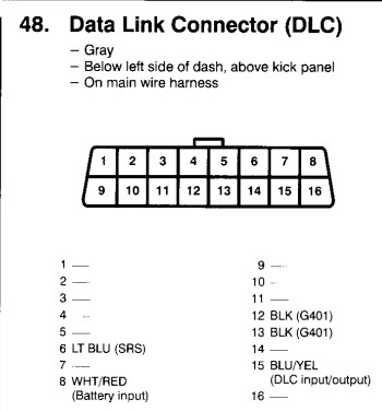 Honda OBD2 Connector Pinout Diagram. Pin 7 is ISO 9141-2 K-Line, and Pin 15 is ISO 9141-2 L-Line, as per OBDII standard. Diagram showing pin assignments for diagnostic communication in OBD2 compliant vehicles.
Important Considerations for 1997 Honda Models:
- Pin 7 (K-Line) and Pin 15 (L-Line) Confusion: As highlighted in the original query, there can be confusion regarding pins 7 and 15. Standard OBD2 dictates pin 7 as the K-Line. In some Honda implementations around 1997, and as observed in later models too, the K-Line might be connected to pin 15 instead of pin 7, or potentially both are used or internally routed differently within the vehicle’s ECU and wiring harness. This deviation from the standard can cause diagnostic tools that assume standard pinouts to fail to communicate.
- 3-Pin DLC Legacy: Prior to OBD2, Honda used a 2 or 3-pin DLC. Some 1997 models might still incorporate elements of this older system alongside or in transition to the 16-pin OBD2. While you should be looking for a 16-pin connector for OBD2, understanding the legacy systems is useful context.
- Software and Protocol Compatibility: Even with the correct pinout, the diagnostic software and the communication protocol it uses must be compatible with the 1997 Honda ECU. Generic OBD2 software might not fully support Honda-specific protocols or older ISO 9141-2 implementations perfectly.
Troubleshooting OBD2 Connection Issues on a 1997 Honda
If you’re facing issues connecting a standard OBD2 scanner to a 1997 Honda, consider these troubleshooting steps:
- Verify Pinout: Use a multimeter to check the actual pinout of your Honda’s DLC. Compare it against both the standard OBD2 pinout and any Honda-specific pinout diagrams you can find for 1997 models. Focus especially on confirming the presence and activity of K-Line (and potentially L-Line) signals on pins 7 and 15.
- Check for Bridging or Non-Standard Wiring: Inspect for any signs of non-standard wiring or bridging between pins in the DLC, which could indicate modifications or a manufacturer-specific setup.
- Software Compatibility: Ensure your diagnostic software is compatible with older OBD2 protocols like ISO 9141-2 and ideally has enhanced Honda-specific support. Software like Hondash or professional scan tools might offer better compatibility than generic OBD2 readers for older Hondas.
- Tool Compatibility: Test with different OBD2 scan tools if possible. Some scanners might handle pinout variations or protocol interpretations more effectively than others.
- Consult Service Manuals: Refer to the Honda service manual for the specific 1997 model you are working on. Wiring diagrams and diagnostic information within the manual are invaluable for confirming pinouts and troubleshooting communication issues.
Conclusion
Diagnosing a 1997 Honda requires a nuanced approach to OBD2. While it should theoretically adhere to the standard, the transition era and potential Honda-specific implementations mean verifying the OBD2 pinout, especially the K-Line configuration, is critical. By understanding the potential variations and using the correct diagnostic tools and software, you can effectively read ECU data and troubleshoot your 1997 Honda. Remember to always consult reliable sources and service manuals for the most accurate information related to your specific vehicle model.