Electronic Throttle Body (ETB) and Accelerator Pedal Position (APP) systems, while seemingly complex, are based on straightforward principles. Understanding these foundational concepts is key to effectively servicing the diverse range of vehicles equipped with these technologies. Using the 2016 Nissan Frontier with a 4.0-liter, 24-valve engine as a model, this guide will explore common approaches to diagnosing both typical and less frequent throttle control issues, with a specific focus on interpreting Etb Obd2 Codes.
Understanding Shared Signals in ETB Systems
In modern vehicles, the driver’s demand for throttle opening is communicated to the engine control module (ECM) via dual Accelerator Pedal Position (APP) sensors. In some designs, a separate module may handle ETB control, but for simplicity, we’ll refer to a single “module” encompassing both configurations. These APP sensors transmit signals to the control module, which in turn regulates the throttle plate position within the ETB. This regulation is achieved by employing a 12-volt, pulse-modulated power supply that works against the throttle plate’s clock spring mechanism. Real-time throttle plate position is then relayed back to the module through two Throttle Position Sensors (TPS). As the pulse modulation duty cycle increases, the throttle plate opens incrementally to meet the APP command.
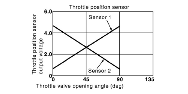
The Nissan Frontier, like many vehicles, utilizes two APP voltage outputs: one ascending and one descending (as illustrated in Photo 1). The ECM cross-references these signals to ensure accuracy at their intersection point. Similarly, the ETB incorporates dual throttle position sensors, also with ascending and descending voltage outputs, to validate the commanded throttle plate position. Discrepancies in the intersection points of either APP or ETB sensor signals will trigger the storage of a Diagnostic Trouble Code (DTC), and typically activate the “check engine” light and potentially an electronic throttle malfunction warning light on the dashboard.
Fail-Safe Mode and OBD2 Code Implications
When the ascending and descending signals from the APP or ETB sensors fail to align as expected, the control module initiates a “fail-safe” or limp mode. In Nissan vehicles, this mode typically fixes the throttle plate opening to a minimal setting, around five degrees. This limp mode can also be activated by transient electrical faults within the ETB or APP circuits. Vehicle speed in fail-safe mode is intentionally restricted, often to between 10 and 30 mph on level surfaces, depending on the vehicle application.
The activation of limp mode is almost always accompanied by specific OBD2 codes related to the ETB system. These codes are crucial for diagnosing the root cause of the problem. Common OBD2 codes associated with ETB and APP issues include those in the P00XX, P01XX, P02XX, and P21XX ranges. For example, codes like P0068 (MAP/MAF – Throttle Position Correlation), P0121 (Throttle/Pedal Position Sensor/Switch A Circuit Range/Performance), P0221 (Throttle/Pedal Position Sensor/Switch B Circuit Range/Performance), and P2135 (Throttle/Pedal Position Sensor/Switch A/B Voltage Correlation) directly point to potential problems within the ETB and APP system. Understanding these codes is the first step in effective diagnosis.
ETB Maintenance and Preventing Fault Codes
A slight clearance is intentionally designed between the throttle plate and throttle bore at closed throttle. This ensures a minimal, predetermined airflow, known as “base air,” which is essential for idle speed management and factored into the ETB’s idle speed calculations (see Photo 2).
The ETB/APP module relies on consistent closed-throttle voltage readings from its throttle position sensors. Inconsistent readings, often due to carbon buildup or contamination, can lead to default operating modes and trigger OBD2 codes. Furthermore, carbon deposits reducing base airflow can disrupt idle speed calculations, resulting in issues like cold stalling and unstable hot idle speeds. Regular ETB cleaning is therefore preventative maintenance that can help avoid ETB related OBD2 codes.
Routine ETB cleaning can be performed by turning the ignition to the “on” position (engine off) and fully depressing the accelerator pedal to open the throttle plate for access. For more severe carbon buildup, ETB removal may be necessary. Use a recommended throttle body cleaner applied to the backside of the throttle plate and inner bore, and gently remove carbon with a toothbrush. Avoid harsh solvents or aerosol carburetor cleaners, as they can damage throttle shaft seals and protective coatings on the throttle plate and bore.
Leveraging Service Information and OBD2 Codes for Diagnosis
The initial step in addressing any throttle-related issue is to connect a scan tool and retrieve stored Diagnostic Trouble Codes (DTCs). While generic P0-series and manufacturer-specific P1-series ETB codes are relatively limited, the P2-series codes offer a more detailed and comprehensive set of diagnostics. These codes generally provide sufficient information to pinpoint sensor and circuit problems within the ETB or APP system. While scan tool code definitions offer a starting point, consulting the code enable criteria in service information is crucial for understanding the specific conditions under which a code is set, and for accessing detailed diagnostic procedures.
Modern scan tools often provide enhanced data streaming capabilities, allowing technicians to monitor live data from the APP and TPS sensors. Comparing the values of the ascending and descending sensors in real-time can reveal discrepancies not immediately apparent from a static code reading. Furthermore, some advanced scan tools offer bi-directional control, enabling technicians to command the ETB to specific positions and observe the system’s response, further aiding in diagnosis and validation of repairs.
Wiring Diagrams: Essential for ETB Code Diagnostics
When diagnosing ETB related OBD2 codes, wiring diagrams are indispensable. They illustrate the electrical interconnections between the ETB, motor drive, throttle position sensors, APP system, and the control module (see Photos 3 and 4). Wiring diagrams, combined with power flow and ground location charts, clearly delineate power sources, reference voltages, communication bus networks, and ground circuits. Understanding these electrical relationships is critical for systematically troubleshooting circuit-related ETB codes.
For instance, a code indicating a TPS circuit malfunction requires tracing the wiring from the sensor back to the ECM, checking for continuity, shorts to ground or voltage, and proper reference voltage supply. Wiring diagrams are essential for identifying the correct pins and test points for these measurements.
Addressing Intermittent ETB Failures and Ghost Codes
Many ETB problems trigger codes, illuminate warning lights, and activate limp mode. However, intermittent faults can be more challenging. Sometimes, normal throttle operation may return after cycling the ignition. This suggests a transient or random failure that is not consistently reproducible. These intermittent issues can still store “ghost codes” in the ECM’s memory, which, while not currently active, can provide valuable clues. Using a scan tool to retrieve historical codes, even if the check engine light is currently off, can uncover these intermittent fault patterns.
Connectivity Issues and Connector Corrosion
Vibration and stress can lead to fretting corrosion within electrical connectors, creating voltage drops at ETB connector pins. Intermittent failures, particularly those occurring during sharp vehicle maneuvers, are frequently caused by connector problems in the ETB/APP circuits. The ideal repair involves addressing the root cause of connector failure and replacing both male and female connector halves. In practice, cleaning connectors with electrical contact cleaner and applying dielectric or high-temperature synthetic grease to the pins is a common interim solution to mitigate future corrosion. When diagnosing ETB OBD2 codes, especially intermittent ones, always inspect connector integrity as a potential source of the problem.
Cold Weather ETB Failures and Grounding Problems
ETB/APP systems typically ground to the engine block, which in turn grounds to the battery’s negative terminal. During cold engine cranking, starter motor current draw can cause a significant amperage spike through the battery/engine block ground connection. If this ground connection is corroded or compromised, the amperage spike can overload it, potentially causing the ETB/APP module to enter limp mode immediately after engine start.
The ETB/APP module might interpret this amperage reduction as an open-circuit condition, potentially setting ETB/APP specific codes or general voltage supply codes. Suspected grounding issues should be addressed by disassembling the block ground connection, thoroughly cleaning cable and block surfaces, applying anti-corrosion compound, and reassembling using star washers and a new retaining bolt to ensure a robust, low-resistance ground path.
Connector Pinout Verification for Accurate Diagnosis
Occasionally, replacing an ETB or APP sensor fails to resolve an idle speed control problem or clear persistent OBD2 codes. Before assuming component failure, perform a key-on, engine-off connector pin-out test at the ETB or APP connector using wiring diagrams or connector pin charts. Verify voltage, ground, and signal integrity at each pin to rule out wiring harness issues or ECM driver problems.
One case involved a persistent high idle speed where the 5-volt reference voltage to the throttle sensors was missing at the ETB connector. Consulting the wiring diagram revealed that the ETB shared its 5-volt reference with the electronic oil pressure sensor. Further investigation traced the fault to a short to ground within the oil pressure sensor, which was pulling down the 5-volt reference for both sensors. Replacing the faulty oil pressure sensor resolved the high idle speed and related codes.
Vacuum Leaks and Unexpected ETB Behavior
In rare instances, vacuum leaks can indirectly affect ETB operation and trigger unusual OBD2 codes or symptoms. One example involved a random 1,600-rpm fast idle condition on a domestic vehicle, consistently occurring after extended brake operation. The stored code indicated a “gross vacuum leak.” Despite smoke and propane testing failing to locate any leaks, a customer’s remark about amateur sound system wiring led to the discovery of a drilled hole through the firewall into the vacuum brake booster, made during a poorly executed aftermarket audio installation.
The ETB’s control strategy, in this case, seemed to fast-idle the engine to compensate for the vacuum leak and ensure adequate brake booster vacuum. Replacing the damaged brake booster resolved the random fast idle and the vacuum leak code. This highlights that even seemingly unrelated systems can interact and influence ETB operation and diagnostics.
In conclusion, while diagnosing electronic throttle control systems and interpreting ETB OBD2 codes might appear daunting, a systematic approach grounded in fundamental understanding, coupled with the use of wiring diagrams, scan tools, and thorough diagnostic procedures, makes even the most “uncommon failures” manageable.
~Gary Goms is a former educator and shop owner with extensive experience in the aftermarket service industry. He is an ASE-certified Master Automobile Technician (CMAT) and holds the L1 advanced engine performance certification. Gary is also a member of the Automotive Service Association (ASA) and the Society of Automotive Engineers (SAE).
Article adapted from ImportCar magazine.