This post details the journey of creating a Heads-Up Display (HUD) for a car using an ESP8266 and an OBD2 reader. The initial phase involved selecting and testing components, which presented some unexpected hurdles, particularly with the display.
Initially, an OLED screen was chosen for displaying vehicle data. However, after connecting and initializing it with DIYMall libraries, the results were disappointing. Instead of a clear display, only random pixels illuminated, failing to turn off even after initialization. This setback indicated a faulty unit, requiring a change in display strategy for the OBD2 reader HUD project.
To ensure display reliability for the ESP8266 OBD2 HUD, a replacement OLED screen was sourced. After researching alternatives, a highly-rated OLED screen compatible with the Adafruit library was selected from Amazon. This decision aimed to leverage established libraries and positive user reviews, increasing the chances of a successful display integration for the car HUD.
Beyond display considerations, power protection was also addressed. To safeguard the system, a 2A fast blow fuse was incorporated for the +12V power supply from the car’s electrical system. Choosing a fast blow fuse is crucial for protecting sensitive electronics from sudden power surges. Paired with 5x20mm fuse PCB mounts, this setup provides a robust and easily maintainable power protection solution for the OBD2 reader and ESP8266 HUD.
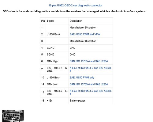
For connecting to the car’s OBD2 port, an extension cable was utilized. Understanding the OBD2 pinout is essential for correctly interfacing with the vehicle’s diagnostic system. Analysis of the car-side OBD2 connector pinout revealed that only five pins were necessary for this project: +12V, Chassis Ground, Signal Ground, CAN High, and CAN Low. These pins are crucial for power and data communication between the car’s computer and the ESP8266 OBD2 reader.
With the required OBD2 pins identified, the next step involved examining the OBD2 extension plug. By carefully inspecting the pin labeling on the extension plug and using a multimeter, each wire’s corresponding pin number was determined. This meticulous process ensures accurate wiring and prevents potential damage to the car’s electronics or the ESP8266 system. Each identified wire was then labeled with tape and a marker for easy identification during the HUD assembly.
In an innovative approach to the HUD aspect, scope lens protectors used in gun sights were considered. These small, transparent pieces of glass or plastic are designed to mount on rails in front of gun sights. The idea is to potentially repurpose these as a display surface for projecting the ESP8266 OLED screen data, creating a functional and unique HUD for the vehicle.
The next steps in this ESP8266 OBD2 reader HUD project involve practical testing. First, the labeled OBD2 extension plug will be connected to the car’s OBD2 port to verify the identified pin connections. Secondly, the new replacement OLED screen will be thoroughly tested to confirm its functionality and suitability for displaying vehicle data in the DIY car HUD. These tests are crucial to move forward with the project and realize the vision of an ESP8266 powered Heads-Up Display.