For automotive enthusiasts and professional tuners leveraging dynamometers for performance analysis, seamless data acquisition is paramount. Modern dyno software often integrates with vehicle’s On-Board Diagnostics (OBD2) system, allowing for real-time monitoring of crucial engine parameters. This article delves into the intricacies of establishing a Dyno Obd2 connection using PEREK dyno software, ensuring you can effectively harness this powerful diagnostic tool.
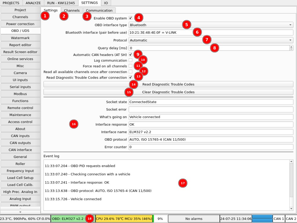
The software facilitates reading diagnostic data directly from your vehicle’s OBD/UDS interface. Connectivity is versatile, supporting both wired USB and wireless Bluetooth interfaces. Configuration of your OBD/UDS system is conveniently managed within the SETTINGS / OBD / UDS section of the software.
Let’s break down the OBD configuration interface:
- Interface Setting Tab: This is your primary area for choosing and configuring your connection type.
- Channels Configuration Tab: Customize the specific data channels you wish to monitor from the vehicle’s ECU (Engine Control Unit).
- Communication Log: A valuable tool for troubleshooting connection issues by providing a detailed log of data exchange.
- Main OBD System Switch: A simple on/off toggle to quickly enable or disable the OBD system, useful for resets or when not in use.
- Interface Type Selection: Choose your connection method here:
- Bluetooth: For wireless OBD2 adapters, offering flexibility and ease of use.
- USB / Serial: For basic OBD2 interfaces utilizing standard serial communication protocols.
- USB / FT2xx: For interfaces that employ the FTDI chip for USB communication, often found in higher-performance adapters.
- Device Selection: The software will list available devices based on your interface type. Right-click to select your specific OBD2 adapter.
- OBD Protocol Selection: Typically set to “Automatic” for hassle-free connection. Manual selection is available for faster connections or if automatic detection fails.
- Query Delay: Adjusting this delay can resolve data mixing issues on fast OBD interfaces by spacing out ECU queries.
- Automatic ECU Header Detection and Physical Addressing: Another method to prevent data mix-ups on high-speed interfaces, ensuring accurate data retrieval.
- Communication Logging Switch: Enable this for in-depth troubleshooting, but keep it disabled during normal operation to conserve system resources.
- Force Simple Channel Reading: This option reads channels one-by-one, disregarding priorities and availability, useful for specific diagnostic scenarios.
- Force Single Read of Available Channels: Initiates a single data read from all channels reported as available by the vehicle, useful for initial setup and verification.
- Enable DTC Reading on Connection: Automatically retrieves Diagnostic Trouble Codes (DTCs) upon connection. Addressing DTCs is crucial as they can impact engine performance and data availability.
- Manually Read DTCs: Allows you to request DTCs at any time during your dyno session.
- Clear DTCs: Provides the ability to clear existing DTCs from the vehicle’s ECU. Exercise caution when using this feature.
- Current OBD Connection Information: Displays real-time status and details of your OBD connection.
- Event Log: Provides a basic troubleshooting log for connection-related events.
- Status Bar OBD Button: A quick indicator of OBD status and a toggle switch (click to enable/disable OBD – same as checkbox 4).
Moving on to channel customization, the Channels tab is where you fine-tune the data you want to monitor.
Here’s a breakdown of the channel configuration options:
- Channel Name: A descriptive name for each data parameter (e.g., Engine RPM, Coolant Temperature).
- Main Command: The OBD2 PID (Parameter ID) command sent to the vehicle to request this specific data.
- Custom Header: Optional field for specifying a custom header if required for certain ECUs or protocols.
- Commands Before Main Command: Commands sent prior to the main command, sometimes necessary for specific ECU communication sequences.
- Commands After Main Command: Commands sent after the main command, for post-data retrieval actions if needed.
- Equation: Allows for applying a formula to calculate the actual channel value from the raw data received (e.g., converting raw sensor voltage to temperature).
- Support Bit Position: For PIDs that contain multiple data channels within a single response, specify the bit position for this particular channel.
- Input Unit: The unit of measurement for the calculated channel value (e.g., RPM, °C, PSI).
- Readout Priority: Determines how frequently this channel is updated. Higher priority channels are updated more often.
- Override Vehicle Parameter Channel: Allows you to replace a built-in vehicle parameter channel with the value from this custom channel.
A crucial first step is to populate your channel list with standard OBD2 parameters. Right-click within the channel list and select “Import from website.” Choose “OBD2 service 01 standard PIDs” and click “OK” to import a comprehensive list of common parameters.
Next, prioritize the channels based on your monitoring needs. Right-click on a channel and select a priority level:
- 0/1: Channel disabled (no updates).
- 1/1: Highest priority – updated as frequently as possible. Ideal for fast-changing parameters like “Timing advance.”
- 1/2 – 1/1000: Lower priorities, updated less frequently. For example, “Engine coolant temperature” might be suitable for a 1/100 priority as it changes relatively slowly.
Remember that update rates are limited by OBD2 communication speed and the number of channels being monitored. Even with high priority settings, a large number of channels will distribute the update frequency.
For advanced troubleshooting and deeper understanding of the data exchange, the Communication tab provides a real-time view of the OBD communication log when the “Log communication” option is enabled.
Connecting via USB Interfaces: Serial and FT2xx
USB / Serial Connection Procedure
- In the OBD interface type dropdown, select USB / Serial.
- Right-click in the USB / Serial interface port selection box and choose the appropriate port (e.g., ttyUSB0).
- Verify that the baud rate setting matches your OBD2 interface’s specification. 34800 is a common baud rate.
USB / FT2xx Connection Procedure
- Select USB / FT2xx as the OBD interface type.
- Right-click in the FT2xx interface selection box. If no devices appear, your interface might not use FT2xx, and you should try the USB / Serial option.
- Confirm the baud rate. While 34800 is typical, some interfaces, like OBD Link EX, use higher rates (e.g., 115200).
Establishing a Bluetooth Dyno OBD2 Connection
For wireless convenience, Bluetooth offers a streamlined dyno OBD2 connection.
Bluetooth Pairing via System Manager
- Ensure your OBD2 Bluetooth interface is plugged into the vehicle’s OBD2 port and the vehicle ignition is turned ON to power the adapter. Position the adapter as close to the dyno controller as possible, minimizing obstructions.
- Initiate pairing from your operating system’s Bluetooth manager. Click the Bluetooth icon (often in the system tray) and select “Add Device…” or similar.
- Wait for your OBD2 interface to appear in the device list. If it doesn’t, check the adapter’s power and proximity.
- Select your interface from the list and click “Pair.”
- Enter the PIN code for your Bluetooth OBD2 adapter. Common PINs are “1234” or “0000.” Click “OK.”
The system may indicate that it doesn’t know how to use the device – this is normal. The dyno software will handle the connection.
Bluetooth Pairing via Blueman Manager
If using Blueman Bluetooth manager:
- Click the Bluetooth icon and select “Devices…”.
- In the Blueman window, click “Search” and wait for your device to appear.
- Right-click on your device and select “Pair.”
- Enter the PIN code (e.g., “1234” or “0000”) and click “OK.”
Pairing is now complete.
Connecting in Dyno Software
- In the dyno software, choose Bluetooth as the OBD interface type.
- Right-click in the Bluetooth interface selection box and select your paired OBD2 adapter (it will likely be listed with its Bluetooth address, e.g., AA:BB:CC:DD:EE:FF = Adapter Name).
- Allow time for the Bluetooth connection to establish within the software.
Enhancing Bluetooth Range with an External Adapter
In situations where the dyno controller is housed in a metal enclosure, Bluetooth signal strength can be significantly reduced. To improve dyno OBD2 Bluetooth connectivity, consider using an external USB Bluetooth dongle with a USB extension cable. Dongles based on the “CSR8510 A10” chip have been tested and proven to work reliably.
To utilize an external Bluetooth adapter, you’ll need to disable the internal Bluetooth module. Edit the /boot/firmware/config.txt file using the command:
sudo nano /boot/firmware/config.txtAdd the following line at the end of the file and reboot your system:
dtoverlay=disable-btBy following these detailed steps, you can confidently establish a robust dyno OBD2 connection, unlocking the full potential of your dyno software for accurate vehicle performance diagnostics and tuning.