Are you looking to connect directly to your vehicle’s diagnostic system without relying on pre-made, potentially expensive tools? For car enthusiasts and DIY mechanics, understanding and accessing your car’s On-Board Diagnostics (OBD) is crucial. This guide walks you through creating a custom Dvi D To Obd2 Pin Out adapter, allowing for direct connection to your vehicle’s CAN bus and power. Please note: this project involves working with automotive electronics and should be undertaken with caution. Disclaimer: This is a DIY guide for informational purposes only. I am not an expert, and this guide is based on my personal experience. Follow these steps at your own risk. I am not responsible for any damage to your vehicle or equipment resulting from this procedure.
Before we begin, let’s gather the necessary tools and parts.
Tools Required:
- Wire strippers/cutters
- Needle-nose pliers
- Molex crimping tool (optional, soldering recommended)
- Soldering iron (recommended for a more secure connection)
Parts List:
- 4-Pin Connector (Link to part; suitable for 22-16AWG wire; insulation/seal size: 1.3-1.7mm)
- OBD-II Cable (Link to part)
For those who prefer to source components individually, you can purchase a female OBD-II connector and use spare wires to connect it to the 4-pin connector. Ensure your wire gauge is compatible with the 4-pin connector you choose.
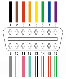
From the OBD-II connector’s 16 pins (referred to as OBD2C), we will utilize only four essential connections for this DVI D to OBD2 pin out configuration:
- Pin 4: Chassis Ground (Orange wire on OBD2C)
- Pin 6: CAN (J-2234) High (Green wire on OBD2C)
- Pin 14: CAN (J-2234) Low (Brown wire with white stripe on OBD2C)
- Pin 16: Battery Power (Green wire with white stripe on OBD2C)
Step-by-Step Guide to Building Your DVI D to OBD2 Pin Out Adapter
1. Preparing the OBD-II Cable Wires
According to established practices, twisting pairs of wires can reduce electromagnetic interference. Begin by carefully removing the outer sheath and shielding from the OBD2C cable. Separate the four wires we’ll be using from the rest. Secure the remaining 12 wires out of your working area using a zip tie to keep them organized and prevent them from interfering with the process.
2. Preparing the 4-Pin Connector Pins
A slight incompatibility arises with the chosen parts: the OBD2C wires are 26AWG, while the 4-pin connector (referred to as 4PC) pins are designed for 22AWG wires. To compensate for the thinner gauge, carefully strip approximately 3/8″ of insulation from the end of each of the four OBD2C wires. Fold the exposed wire back onto itself and twist to effectively thicken it, ensuring a better fit within the 4PC pin. Slide one of the provided rubber seals onto each wire to provide environmental protection at the connector.
3. Attaching Wires to Connector Pins
The 4PC pins feature two sets of prongs. The front prongs are designed to crimp onto the exposed wire, while the rear prongs secure the wire’s seal. Insert the prepared wire into the front section of the pin, ensuring it aligns with the first set of prongs. Due to the small gauge of the wire, using needle-nose pliers to hold the wire in position during the next step is highly recommended for precision and stability.
4. Soldering the Wire to the Pin (Recommended)
Soldering provides a robust and electrically sound connection, which is particularly beneficial given the fine wires. While crimping is an option (step 5), soldering enhances the connection’s reliability. If you choose to solder, apply solder to the area where the wire meets the pin’s prongs. Ensure the solder flows smoothly, creating a strong bond. If you are new to soldering, online resources like YouTube offer helpful tutorials to improve your technique.
5. Crimping the Connector (Alternative to Soldering)
If you prefer crimping or lack soldering equipment, use a Molex crimping tool for the best results. However, for a one-time project, needle-nose pliers can be used as a substitute. Position the wire within the front prongs of the 4PC pin. Using angled needle-nose pliers, carefully fold one prong over the wire, followed by the other. For added security, you can further compress the prongs with the pliers to ensure a tight mechanical connection.
6. Securing the Rubber Seal
Slide the rubber seal forward until it sits between the rear set of prongs on the 4PC pin. Employ the same crimping technique used in step 5 to fold these prongs over the rubber seal. This secures the seal in place, providing strain relief and environmental protection for the connection.
7. Wire Pairing and Twisting
Although the exact reason isn’t definitively stated, many DIY guides recommend twisting specific wire pairs, possibly to minimize electromagnetic interference or crosstalk. Pair and twist the wires as follows:
- Pin 4 (Orange) with Pin 16 (Green with white stripe)
- Pin 6 (Green) with Pin 14 (Brown with white stripe)
8. Inserting Pins into the 4-Pin Connector Housing
Insert the prepared pins into the 4PC housing in the correct orientation as shown below. Ensure you are referencing the connector slot labels (A, B, C, D) for proper DVI D to OBD2 pin out configuration:
- Pin 14 (Brown with white stripe) into connector slot A
- Pin 6 (Green) into connector slot B
- Pin 16 (Green with white stripe) into connector slot C
- Pin 4 (Orange) into connector slot D
Push each pin into the rear of the connector housing until you hear an audible click, indicating that the pin is securely locked in place. Using needle-nose pliers can aid in gently pulling the wire from the rear to ensure the pin is fully seated and locked.
Your DIY DVI D to OBD2 Pin Out Adapter is Complete!
This custom-built adapter has been successfully tested to read and clear diagnostic trouble codes.
If any step in this guide is unclear, please ask for clarification. Additional photos or more detailed explanations can be provided to assist you in building your DVI D to OBD2 pin out adapter.