Confused about how your car communicates diagnostic information? If you’re diving into the world of On-Board Diagnostics (OBD2), you’ve likely encountered hexadecimal. In this guide, we’ll clarify whether global OBD2 uses hexadecimal, and how this number system is fundamental to understanding your vehicle’s data. We’ll explore the OBD2 protocol, its parameters (PIDs), and its connection to the CAN bus, all while demystifying the use of hexadecimal in automotive diagnostics.
This article provides a practical introduction to OBD2, focusing on data interpretation and the role of hexadecimal. You’ll learn how to request and decode OBD2 data, understand key use cases, and gain practical tips for working with your car’s diagnostic system.
Discover why this is considered a top resource for understanding OBD2 and hexadecimal in automotive diagnostics.
You can also explore our introductory video on OBD2 or download this guide in PDF format for offline access.
Understanding OBD2 and Hexadecimal: A Deep Dive
OBD2, or On-Board Diagnostics version 2, is essentially your car’s internal health monitoring system. It’s a standardized protocol that allows mechanics and car enthusiasts alike to retrieve diagnostic trouble codes (DTCs) and access real-time data from your vehicle. This communication happens through the OBD2 connector, using a language that heavily relies on hexadecimal representation.
Have you ever seen the check engine light illuminate on your dashboard?
That’s OBD2 in action, signaling a potential issue. When you take your car to a repair shop, a technician uses an OBD2 scanner to pinpoint the problem.
This involves connecting an OBD2 reader to the 16-pin OBD2 connector, usually found near the steering wheel. The scanner sends ‘OBD2 requests’ to your car, and the car responds with ‘OBD2 responses’. These responses contain crucial data like speed, fuel level, and, importantly, Diagnostic Trouble Codes (DTCs). And yes, much of this data, including PIDs and DTCs, is represented in hexadecimal. This system allows for faster and more accurate troubleshooting.
Alt text: OBD2 system diagram showing malfunction indicator light (MIL) on dashboard and a technician using a scan tool connected to the OBD2 port.
OBD2 Compatibility: Is Your Car Included?
The short answer is: Very likely!
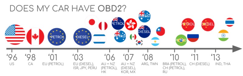
Almost all modern gasoline and diesel cars, excluding electric vehicles in some respects, are equipped with OBD2 and often operate on the CAN bus network. However, for older vehicles, even if you spot a 16-pin OBD2 connector, it doesn’t automatically guarantee full OBD2 compliance. Some may still lack complete OBD2 functionality. A key indicator of OBD2 compliance is the vehicle’s manufacturing year and region of sale:
Alt text: OBD2 compliance chart by region showing mandatory years for OBD2 adoption in US and EU for gasoline and diesel vehicles.
A Brief History of OBD2 and Emission Standards
OBD2’s origins trace back to California. The California Air Resources Board (CARB) mandated OBD in all new cars starting from 1991 to monitor and control vehicle emissions.
The Society of Automotive Engineers (SAE) further developed the OBD2 standard, standardizing DTCs and the physical OBD connector across different car manufacturers (SAE J1962).
The OBD2 standard was implemented globally in phases:
- 1996: OBD2 became mandatory in the USA for all cars and light trucks.
- 2001: The European Union required OBD2 for gasoline cars.
- 2003: The EU extended the requirement to diesel cars as well (EOBD – European On-Board Diagnostics).
- 2005: OBD2 was mandated in the US for medium-duty vehicles.
- 2008: US vehicles were required to use ISO 15765-4 (CAN) as the foundation for OBD2 communication.
- 2010: OBD2 became mandatory for heavy-duty vehicles in the US.
This historical progression underscores the global adoption of OBD2 as a crucial tool for emission control and vehicle diagnostics. Understanding this history helps appreciate why OBD2 data is structured the way it is, including the use of hexadecimal to efficiently represent diagnostic information.
Alt text: OBD2 history infographic timeline highlighting key milestones in OBD2 adoption for emission control across different regions.
Alt text: OBD2 history timeline graphic summarizing the evolution of on-board diagnostics from OBD to OBD2.
Alt text: OBD3 future concept visualization showing remote diagnostics, emissions testing, cloud integration, and IoT connectivity for vehicles.
The Future of OBD2: Trends and Challenges
OBD2 is expected to remain relevant, but its form and application are evolving.
Here are some key trends shaping the future of OBD2:
While legislated OBD2 was initially designed for emission control and testing, electric vehicles (EVs) present a shift. Interestingly, most modern EVs don’t fully support standard OBD2 requests. Instead, they often use OEM-specific UDS (Unified Diagnostic Services) communication protocols. This makes generic OBD2 tools less effective for EVs, requiring specialized knowledge and tools to decode their data. However, communities are working on reverse engineering efforts, as seen in case studies for electric cars like Tesla, Hyundai/Kia, Nissan, and VW/Skoda EVs.
Recognizing the limitations of current OBD2 implementations in terms of data richness and lower-layer protocols, alternatives like WWH-OBD (World Wide Harmonized OBD) and OBDonUDS (OBD on UDS) are emerging. These aim to improve OBD communication by using the UDS protocol as a base, promising more streamlined and enhanced diagnostic capabilities. For more on these advanced protocols, refer to our introduction to UDS.
In our increasingly connected world, traditional OBD2 testing methods can be inefficient. Manual emission checks are time-consuming and costly.
The proposed solution is OBD3 – integrating telematics into vehicles.
OBD3 envisions adding a small radio transponder to all cars, similar to those used for bridge tolls. This would enable vehicles to wirelessly transmit their vehicle identification number (VIN) and DTCs via WiFi to a central server for automated checks.
Many devices today already facilitate CAN or OBD2 data transfer via WiFi or cellular networks, such as the CANedge2 WiFi CAN logger and the CANedge3 3G/4G CAN logger.
While offering convenience and cost savings, OBD3 raises privacy concerns due to potential surveillance implications, presenting a political challenge.
Originally intended for stationary emission controls, OBD2 is now widely used by third parties to access real-time vehicle data through OBD2 dongles, CAN loggers, and similar devices. However, the German car industry is advocating for changes that could restrict this access.
BMW’s SVP of Electronics, Christoph Grote, stated in 2017:
“OBD has been designed to service cars in repair shops. In no way has it been intended to allow third parties to build a form of data-driven economy on the access through this interface“
The proposal suggests disabling OBD2 functionality during normal driving and instead centralizing data collection through manufacturer servers. This would give automakers greater control over ‘automotive big data’.
Arguments for this shift include enhanced security, aiming to reduce the risk of car hacking. However, critics view this as a commercially motivated move to control valuable vehicle data, potentially disrupting the market for third-party OBD2 services. The future of OBD2 data access remains uncertain, but these trends highlight significant shifts in the automotive diagnostic landscape.
Alt text: OBD2 connector removed from EV port illustrating limited OBD2 access in electric vehicles and OEM-specific protocols.
Enhance Your CAN Bus Knowledge
Want to become proficient in CAN bus technology?
Access our 12 ‘simple introductions’ compiled into a comprehensive 160+ page PDF:
Download the Ultimate CAN Bus Guide Now
Alt text: CAN Bus Ultimate Guide PDF cover image, promoting a 160+ page tutorial for CAN bus expertise.
OBD2 Standards: The Technical Foundation
On-board diagnostics, OBD2, functions as a higher-layer protocol, similar to a language, while CAN acts as the communication method, like a phone line. This makes OBD2 comparable to other CAN-based higher-layer protocols like J1939, CANopen, and NMEA 2000.
OBD2 standards define the OBD2 connector, lower-layer protocols, OBD2 parameter IDs (PIDs), and much more. These standards can be categorized within the 7-layer OSI model. We will focus on the most crucial aspects in the following sections.
In the OSI model context, you’ll notice that both SAE and ISO standards cover multiple layers. This reflects the standards for OBD defined in the USA (SAE) and Europe (ISO). Many standards are technically very similar, for example, SAE J1979 and ISO 15031-5, or SAE J1962 and ISO 15031-3.
Crucially, within these standards, hexadecimal is used to represent data values, addresses, and commands. This is a core aspect of how OBD2 communicates diagnostic information.
Alt text: OBD2 and CAN Bus OSI Model diagram illustrating the 7-layer structure and corresponding ISO and SAE standards for each layer.
Alt text: OBD2 connector pinout diagram showing pin assignments for a Type A female socket Data Link Connector (DLC).
The OBD2 Connector: SAE J1962 Standard
The 16-pin OBD2 connector is your gateway to accessing vehicle data. It is standardized under SAE J1962 / ISO 15031-3.
The illustration above shows a typical Type A OBD2 pin connector (also known as Data Link Connector, or DLC).
Key points to note:
- The connector is generally located near the steering wheel but can sometimes be hidden from immediate view.
- Pin 16 provides battery power, often even when the ignition is off, allowing for diagnostics without the engine running.
- The OBD2 pinout configuration varies depending on the communication protocol used by the vehicle.
- CAN bus is the most prevalent lower-layer protocol, meaning pins 6 (CAN-H) and 14 (CAN-L) are commonly connected in modern vehicles.
OBD2 Connector Types: A vs. B
In practice, you might encounter both Type A and Type B OBD2 connectors. Type A is standard in cars, while Type B is more common in medium and heavy-duty vehicles.
While both types share similar OBD2 pinouts, they differ in power supply outputs (12V for Type A and 24V for Type B). Baud rates can also vary, with cars typically using 500K, while heavy-duty vehicles often use 250K (though 500K support is increasing).
Visually distinguishing them, the Type B OBD2 connector has an interrupted groove in the center. This means a Type B OBD2 adapter cable is compatible with both Type A and B sockets, but a Type A adapter will not fit into a Type B socket.
Alt text: OBD2 Connector Type A vs B comparison showing pinout differences, voltage specifications (12V vs 24V), and typical vehicle applications.
Alt text: OBD2 vs CAN bus ISO15765 diagram illustrating the relationship between OBD2 as a protocol and CAN bus as the communication medium.
OBD2 and CAN Bus: ISO 15765-4 Standard
Since 2008, CAN bus has been the mandatory lower-layer protocol for OBD2 in all US-sold vehicles, as per ISO 15765.
ISO 15765-4 (also known as Diagnostics over CAN or DoCAN) specifies constraints applied to the CAN standard (ISO 11898).
It standardizes the CAN interface for diagnostic equipment, focusing on the physical, data link, and network layers:
- CAN bus bit-rate must be either 250K or 500K.
- CAN IDs can be 11-bit or 29-bit.
- Specific CAN IDs are reserved for OBD requests and responses.
- Diagnostic CAN frame data length is fixed at 8 bytes.
- The OBD2 adapter cable length must not exceed 5 meters.
OBD2 CAN Identifiers: 11-bit and 29-bit
OBD2 communication is based on request/response message exchanges.
In most cars, 11-bit CAN IDs are used for OBD2 communication. The ‘Functional Addressing’ ID is 0x7DF (in hexadecimal), which broadcasts a request to all OBD2-compatible ECUs to report data for the requested parameter (defined in ISO 15765-4). CAN IDs ranging from 0x7E0 to 0x7E7 (also hexadecimal) are used for ‘Physical Addressing’ requests to specific ECUs, though less common.
ECUs respond using 11-bit IDs from 0x7E8 to 0x7EF (hexadecimal). The most frequent response ID is 0x7E8 (from the ECM, Engine Control Module), and sometimes 0x7E9 (from the TCM, Transmission Control Module).
In some vehicles, particularly vans and medium to heavy-duty vehicles, OBD2 communication might use extended 29-bit CAN identifiers instead of 11-bit.
Here, the ‘Functional Addressing’ CAN ID is 0x18DB33F1 (hexadecimal).
Responses in this case typically use CAN IDs from 0x18DAF100 to 0x18DAF1FF (hexadecimal), commonly 0x18DAF110 and 0x18DAF11E. The response ID is sometimes represented in ‘J1939 PGN’ format, specifically PGN 0xDA00 (55808), which the J1939-71 standard designates as ‘Reserved for ISO 15765-2’.
Notice the consistent use of hexadecimal (e.g., 0x7DF, 0x7E8, 0x18DB33F1) in representing CAN IDs and PGNs. This is a key aspect of OBD2 and CAN bus communication.
Alt text: OBD2 request-response frame diagram showing the structure of request and response messages including PID and data parameters.
Alt text: OBD2 CAN bus identifier table highlighting hexadecimal IDs like 7DF, 7E8, and 7E0 for request and response messages.
Alt text: OBD2 vs Proprietary CAN bus diagram illustrating the difference between standardized OBD2 and OEM-specific CAN protocols within a vehicle network.
OBD2 vs. Proprietary CAN Protocols
It’s important to understand that your vehicle’s electronic control units (ECUs) operate using OEM-specific CAN protocols, independent of OBD2. Each car manufacturer develops proprietary CAN protocols tailored to their vehicle brands, models, and years. Without OEM documentation or reverse engineering, interpreting this proprietary CAN data is typically impossible.
When you connect a CAN bus data logger to your car’s OBD2 connector, you might capture OEM-specific CAN data, often broadcast at high rates (1000-2000 frames/second). However, many newer vehicles employ a ‘gateway’ that restricts access to this OEM CAN data, allowing only OBD2 communication through the OBD2 port.
Therefore, think of OBD2 as a separate, standardized higher-layer protocol that runs in parallel with the OEM-specific communication network. It’s designed for diagnostics and emission-related data access, not for accessing the full spectrum of vehicle operational data.
Bit-rate and ID Validation in OBD2
As mentioned, OBD2 can use two bit-rates (250K, 500K) and two CAN ID lengths (11-bit, 29-bit), resulting in four possible combinations. Modern cars commonly use 500K and 11-bit IDs. External tools should systematically validate these parameters.
ISO 15765-4 provides guidelines for an initialization sequence to determine the correct combination. This process relies on the fact that OBD2-compliant vehicles must respond to a mandatory OBD2 request (see the OBD2 PID section) and that incorrect bit-rates cause CAN error frames.
Newer versions of ISO 15765-4 also consider vehicles that might support OBD communication via OBDonUDS instead of OBDonEDS. This article primarily focuses on OBD2/OBDonEDS (OBD on emission diagnostic service as per ISO 15031-5/SAE J1979) rather than WWH-OBD/OBDonUDS (OBD on Unified Diagnostic Service as per ISO 14229, ISO 27145-3/SAE J1979-2).
To test for OBDonEDS vs OBDonUDS, diagnostic tools may send additional UDS requests with 11-bit/29-bit functional address IDs for service 0x22 (hexadecimal) and data identifier (DID) 0xF810 (hexadecimal) – protocol identification. OBDonUDS-compatible vehicles should have ECUs that respond to this DID.
In practice, OBDonEDS (also known as OBD2, SAE OBD, EOBD, or ISO OBD) is prevalent in most non-EV cars today, while WWH-OBD is mainly used in EU trucks and buses.
Alt text: OBD2 bit-rate and CAN ID validation flowchart outlining the steps to automatically detect correct communication parameters based on ISO 15765-4.
Alt text: OBD2 five protocols diagram listing CAN (ISO 15765), KWP2000, SAE J1850, and ISO9141 as lower-layer communication options.
Five Lower-Layer OBD2 Protocols
While CAN (ISO 15765) is now the dominant lower-layer protocol for OBD2, especially in vehicles manufactured post-2008, older cars might use one of four other protocols. Examining the OBD2 connector pinouts can help identify the protocol in use.
- ISO 15765 (CAN bus): Mandatory in US cars since 2008, now widely used.
- ISO14230-4 (KWP2000): Keyword Protocol 2000, common in 2003+ Asian cars.
- ISO 9141-2: Used in EU, Chrysler, and Asian cars from 2000-04.
- SAE J1850 (VPW): Predominantly used in older GM vehicles.
- SAE J1850 (PWM): Mainly found in older Ford vehicles.
ISO-TP for OBD2 Message Transport: ISO 15765-2
All OBD2 data transmission over CAN bus relies on ISO-TP (ISO 15765-2), a transport protocol. ISO-TP enables the transmission of data payloads larger than 8 bytes, which is essential for OBD2 functions like retrieving the Vehicle Identification Number (VIN) or Diagnostic Trouble Codes (DTCs). It handles segmentation, flow control, and reassembly of larger messages. For more details, see our introduction to UDS.
However, much OBD2 data fits within a single CAN frame. In these cases, ISO 15765-2 specifies the use of ‘Single Frame’ (SF) format. The first data byte (PCI field) indicates the payload length (excluding padding), leaving 7 bytes for OBD2-related communication.
Alt text: ISO 15765-2 ISO-TP frame types diagram illustrating Single Frame (SF), First Frame (FF), Consecutive Frame (CF), and Flow Control (FC) frame formats used in OBD2.
Decoding the OBD2 Diagnostic Message: SAE J1979, ISO 15031-5
To fully grasp OBD2 communication on CAN, let’s examine a raw ‘Single Frame’ OBD2 CAN message. Simplified, an OBD2 message consists of a CAN identifier, a data length indicator (PCI field), and the data itself. The data segment is further divided into Mode, parameter ID (PID), and data bytes. All of these components are typically represented in hexadecimal.
Alt text: OBD2 message structure breakdown diagram illustrating the components of an OBD2 frame: Mode, Parameter ID (PID), and Data Bytes.
Example: OBD2 Request and Response in Hexadecimal
Let’s consider an example: requesting ‘Vehicle Speed’.
A diagnostic tool sends a request message to the car with CAN ID 0x7DF (hexadecimal) and 2 payload bytes: Mode 0x01 (hexadecimal) and PID 0x0D (hexadecimal). The car responds with CAN ID 0x7E8 (hexadecimal) and 3 payload bytes, including the vehicle speed value in the 4th byte, 0x32 (hexadecimal, which is 50 in decimal).
By consulting the OBD2 PID decoding rules for PID 0x0D, we determine that the physical value is 50 km/h.
This example clearly shows how hexadecimal is used for CAN IDs, OBD2 modes, and PIDs.
Alt text: OBD2 request response example diagram showing hexadecimal CAN IDs 7DF for request and 7E8 for response in a vehicle speed query.
Alt text: OBD2 PID example diagram for Vehicle Speed (PID 0D) illustrating the hexadecimal PID code and its description.
Alt text: OBD2 service modes diagram outlining the 10 standard diagnostic services or modes in OBD2 protocol.
The 10 OBD2 Services (Modes)
OBD2 defines 10 diagnostic services, also known as modes. Mode 0x01 (hexadecimal) provides current real-time data, while others are used for displaying and clearing diagnostic trouble codes (DTCs) or accessing freeze frame data.
Vehicles are not required to support all 10 OBD2 modes, and manufacturers can implement OEM-specific modes beyond these standard ones.
In OBD2 messages, the mode is located in the second byte. In a request, the mode is included directly (e.g., 0x01), and in the response, 0x40 (hexadecimal) is added to the mode value (e.g., resulting in 0x41).
OBD2 Parameter IDs (PIDs)
Each OBD2 mode contains Parameter IDs (PIDs).
For instance, mode 0x01 (hexadecimal) includes approximately 200 standardized PIDs that provide real-time data on parameters like speed, RPM, and fuel level. However, vehicles don’t necessarily support all PIDs within a mode. In reality, most vehicles support only a subset of the standardized PIDs.
One PID is particularly significant:
If an emissions-related ECU supports any OBD2 services, it must support mode 0x01 PID 0x00 (hexadecimal). Responding to PID 0x00, the ECU indicates support for PIDs 0x01-0x20. This makes PID 0x00 a fundamental ‘OBD2 compatibility test’. Similarly, PIDs 0x20, 0x40, 0x60, 0x80, 0xA0, 0xC0 (all hexadecimal) are used to determine support for subsequent ranges of mode 0x01 PIDs.
Again, note the consistent use of hexadecimal to denote modes and PIDs. This is central to the OBD2 standard.
Alt text: OBD2 request-response frames diagram emphasizing Parameter IDs (PIDs) and data parameters within OBD2 communication.
Alt text: OBD2 PID overview tool screenshot displaying the user interface for service 01 PID lookup and analysis.
Tip: Using an OBD2 PID Overview Tool
SAE J1979 and ISO 15031-5 appendices provide scaling information for standard OBD2 PIDs, enabling you to convert raw data into physical values (as explained in our CAN bus introduction).
For quick lookup of mode 0x01 PIDs, our OBD2 PID overview tool is invaluable. It helps you construct OBD2 request frames and dynamically decode OBD2 responses.
Access the OBD2 PID overview tool here
Practical Guide: Logging and Decoding OBD2 Data
This section provides a hands-on example of logging OBD2 data using the CANedge CAN bus data logger.
The CANedge allows custom CAN frame transmission, making it suitable for OBD2 logging.
Connect the CANedge to your vehicle using our OBD2-DB9 adapter cable for easy setup.
Alt text: OBD2 PID data logger setup diagram illustrating request frame ID 7DF and response frame ID 7E8 for data logging.
The responses to ‘Supported PIDs’ can be reviewed in asammdf
Alt text: OBD2 bit rate test screenshot showing validation of 500K bit rate and OBD2 Supported PIDs Test responses visualized in asammdf software.
Alt text: OBD2 PID lookup tool screenshot displaying supported PIDs results after decoding via online lookup tool.
Step #1: Verify Bit-rate, IDs, and Supported PIDs
As discussed, ISO 15765-4 outlines how to determine the bit-rate and IDs used by a vehicle. You can test this with CANedge as follows (see CANedge Intro for details):
- Transmit a CAN frame at 500K and check for successful transmission (if unsuccessful, try 250K).
- Use the identified bit-rate for subsequent communication.
- Send multiple ‘Supported PIDs’ requests and analyze the responses.
- Response IDs will indicate 11-bit vs. 29-bit CAN ID usage.
- Response data reveals supported PIDs.
We provide ready-to-use configurations to perform these tests efficiently.
Most post-2008 non-EV cars support 40-80 PIDs via 500K bit-rate, 11-bit CAN IDs, and the OBD2/OBDonEDS protocol.
As shown in the asammdf GUI screenshot, multiple responses to a single OBD request are common. This is because using the 0x7DF (hexadecimal) request ID polls all ECUs for responses. Since all OBD2/OBDonEDS-compliant ECUs must support service 0x01 PID 0x00, there are often numerous responses to this PID. Subsequent ‘Supported PIDs’ requests typically receive fewer responses, as seen in the example. Notably, the ECM ECU (0x7E8, hexadecimal) often supports all PIDs supported by other ECUs, so busload can be reduced by directing requests specifically to this ECU using the ‘Physical Addressing’ CAN ID 0x7E0 (hexadecimal) for future communication.
Step #2: Configure OBD2 PID Requests
Once you know your vehicle’s supported OBD2 PIDs, bit-rate, and CAN IDs, configure your transmit list with the PIDs you want to log.
Consider these points:
- CAN IDs: Switch to ‘Physical Addressing’ request IDs (e.g., 0x7E0) to minimize multiple responses per request.
- Spacing: Add 300-500 ms intervals between OBD2 requests to prevent ECU overload and ensure reliable responses.
- Battery Drain: Use triggers to stop transmissions when the vehicle is inactive to avoid unnecessary ECU wake-up and battery drain.
- Filters: Apply filters to record only OBD2 responses, especially if your vehicle also outputs OEM-specific CAN data, to keep logs clean and focused.
With these configurations, your device is set to log raw OBD2 data effectively.
An example list of CANedge OBD2 PID requests configuration.
Alt text: CANedge OBD2 PID request list example screenshot showing configuration of PIDs to request for data logging.
asammdf lets you DBC decode and visualize OBD2 data.
Alt text: OBD2 data visualization in asammdf software showing decoded and plotted data from CAN bus using a DBC file.
Step #3: DBC Decode Raw OBD2 Data
Finally, to analyze and visualize your logged data, you need to decode the raw OBD2 data into ‘physical values’ (e.g., km/h, °C).
Decoding information is in ISO 15031-5/SAE J1979 (and publicly available resources like Wikipedia). For convenience, we offer a free OBD2 DBC file to simplify DBC decoding of raw OBD2 data in most CAN bus software tools.
Decoding OBD2 data is more complex than standard CAN signals because different OBD2 PIDs are transmitted using the same CAN ID (e.g., 0x7E8). Therefore, the CAN ID alone isn’t enough to identify the signals within the payload.
Instead, you must use the CAN ID, OBD2 mode, and OBD2 PID to uniquely identify each signal. This is a form of multiplexing called ‘extended multiplexing‘, which can be implemented using DBC files.
CANedge: Your OBD2 Data Logger Solution
The CANedge makes OBD2 data logging straightforward, recording data to an 8-32 GB SD card. Simply connect it to your vehicle to start logging and decode the data using free software/APIs and our OBD2 DBC.
Learn more about OBD2 logger intro Explore CANedge features
OBD2 Multi-Frame Examples: ISO-TP in Action
OBD2 communication utilizes ISO-TP (transport protocol) as per ISO 15765-2. While many examples are single-frame, multi-frame communication is essential for larger data sets.
Multi-frame OBD2 communication requires flow control frames (see our UDS introduction). A common approach is to send a static flow control frame approximately 50 ms after the initial request frame, as demonstrated in the CANedge configuration example.
Analyzing multi-frame OBD2 responses requires CAN software/API tools that support ISO-TP, such as the CANedge MF4 decoders.
Alt text: OBD2 multi-frame request message screenshot example for requesting Vehicle Identification Number (VIN).
Example 1: Retrieving the OBD2 Vehicle Identification Number (VIN)
The Vehicle Identification Number (VIN) is crucial for telematics, diagnostics, and more (see our UDS introduction). To retrieve the VIN using OBD2, use mode 0x09 (hexadecimal) and PID 0x02 (hexadecimal):
Alt text: VIN Vehicle Identification Number OBD2 multi-frame example diagram illustrating the request and response message flow for retrieving VIN.
The diagnostic tool sends a Single Frame request with PCI field 0x02, request service identifier 0x09, and PID 0x02 (all hexadecimal).
The vehicle responds with a First Frame containing PCI, length (0x014 = 20 bytes, hexadecimal), mode (0x49, i.e., 0x09 + 0x40, hexadecimal), and PID 0x02 (hexadecimal). Following the PID is byte 0x01 (hexadecimal), indicating Number Of Data Items (NODI), which is 1 in this case (see ISO 15031-5 / SAE J1979 for details). The subsequent 17 bytes represent the VIN, convertible from HEX to ASCII as discussed in our UDS introduction.
Example 2: OBD2 Multi-PID Request (6x)
OBD2 allows requesting up to 6 mode 0x01 PIDs in a single request frame. The ECU responds with data for supported PIDs (omitting unsupported ones), potentially using multiple frames via ISO-TP.
This method enhances data collection efficiency, but the signal encoding becomes specific to the request method, making generic OBD2 DBC files less useful. We generally don’t recommend this approach in practice. Here’s an example trace:
Alt text: Multiple OBD2 PID request screenshot example showing a multi-frame ISO-TP trace for requesting multiple PIDs in one request.
The multi-frame response resembles the VIN example, but the payload includes both requested PIDs and their data. The PIDs in the example are ordered similarly to the request order, which is common but not strictly mandated by ISO 15031-5.
Decoding these responses using generic DBC files is challenging. It involves extended multiplexing with payload position dependencies for each PID, making DBC generalization across vehicles difficult. Handling multiple multi-PID requests further complicates DBC management.
Workarounds could involve custom scripts that interpret responses based on request messages, but these are hard to scale.
Example 3: OBD2 Diagnostic Trouble Codes (DTCs)
OBD2 mode 0x03 (hexadecimal), ‘Show stored Diagnostic Trouble Codes’, is used to request emissions-related DTCs. No PID is included in the request. Responding ECUs indicate the number of stored DTCs (potentially zero if none), with each DTC occupying 2 data bytes. Multi-frame responses are necessary when more than 2 DTCs are stored.
The 2-byte DTC value is structured according to ISO 15031-5/ISO 15031-6. The first 2 bits define the ‘category’, and the remaining 14 bits form a 4-digit code (in hexadecimal). Decoded DTC values can be looked up using online OBD2 DTC lookup tools like repairpal.com.
The example below shows a request to an ECU with 6 stored DTCs.
Alt text: OBD2 DTC Diagnostic Trouble Code decoding example diagram explaining the structure and interpretation of DTC codes.
Alt text: OBD2 Diagnostic Trouble Codes DTC CAN Bus Request Response example showing CAN bus trace frames for DTC retrieval.
OBD2 Data Logging: Real-World Use Cases
OBD2 data from cars and light trucks has diverse applications:
Alt text: OBD2 data logger in car vehicle illustration depicting on-board diagnostics and data logging applications.
Car Data Logging
OBD2 data logging from cars can be used for fuel efficiency improvement, driving behavior analysis, prototype testing, and insurance telematics.
Explore OBD2 loggers
Alt text: OBD2 real-time streaming diagnostics illustration via USB interface for vehicle health monitoring.
Real-Time Car Diagnostics
OBD2 interfaces facilitate real-time streaming of human-readable diagnostic data, aiding in vehicle troubleshooting and maintenance.
Learn about OBD2 streaming
Alt text: OBD2 data logger for predictive maintenance illustration showing telematics and IoT applications for vehicle maintenance.
Predictive Maintenance
IoT-enabled OBD2 loggers can monitor cars and light trucks in the cloud, enabling predictive maintenance and preventing breakdowns.
Discover predictive maintenance solutions
Alt text: Black box CAN logger illustration for vehicle event recording in insurance and warranty use cases.
Vehicle Blackbox Logger
An OBD2 logger can serve as a ‘black box’ for vehicles, recording data for dispute resolution, accident analysis, and enhanced diagnostics.
Explore CAN bus blackbox loggers
Do you have an OBD2 data logging use case? Contact us for a free consultation!
Contact us for expert advice
Explore our guides section for more introductions or download the ‘Ultimate Guide’ PDF.
Ready to log or stream OBD2 data?
Get your OBD2 data logger today!
Buy OBD2 Data Loggers Now Contact us for inquiries
Further Reading Recommendations
OBD2 DATA LOGGER: EASILY LOG & CONVERT OBD2 DATA
CANEDGE2 – PRO CAN IoT LOGGER
[