Are you a car enthusiast looking to dive into the world of automotive diagnostics without breaking the bank? Creating your own OBD2 to USB cable is a fantastic DIY project that allows you to connect your car to your computer for reading error codes, monitoring performance data, and much more. This guide will walk you through the process of building your own OBD2 to USB cable, perfect for those who love to tinker with their vehicles.
Disclaimer: Before we get started, it’s crucial to understand that this is a DIY project and involves working with your car’s electronics. I am sharing my personal experience, and while these steps worked for me, I cannot guarantee they will work for everyone. Incorrect wiring can potentially damage your car’s ECU or other components. You are undertaking this project at your own risk. I am not responsible for any damage, malfunctions, or unforeseen interdimensional consequences that may arise from following these instructions.
Tools and Parts You’ll Need
To embark on this DIY journey, gather the following tools and parts:
Tools:
- Wire strippers/cutters
- Needle-nose pliers
- Molex crimping tool (optional, but recommended for professional crimps)
- Soldering iron and solder (recommended for a more secure connection)
Parts:
- 4-Pin Connector (Corsa Technic – 4-Pin Connector) – Choose the correct pin/wire size (22-16AWG) and insulation/seal size (1.3-1.7mm) to match your wire.
- OBD-II Cable (Corsa Technic – OBD-II Cable) – This cable provides the OBD2 connector and pre-attached wires.
Cost-Saving Tip: If you have spare wires of the correct gauge, you can purchase just the female OBD-II connector and wire the 4 necessary connections directly, potentially saving a bit on parts. Ensure your spare wire gauge is compatible with the chosen 4-pin connector.
Understanding the OBD2 Connector Wiring
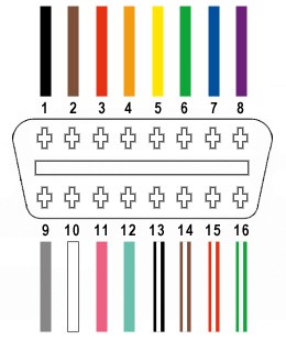
The OBD-II connector (OBD2C) has 16 pins, but for this DIY USB cable, we only need to focus on four essential wires:
- Pin 4: Chassis Ground (often an orange wire on the OBD2C)
- Pin 6: CAN (J-2284) High (often a green wire on the OBD2C)
- Pin 14: CAN (J-2284) Low (often a brown wire with a white stripe on the OBD2C)
- Pin 16: Battery Power (often a green wire with a white stripe on the OBD2C)
These four pins are crucial for basic OBD2 communication, allowing you to interface with your car’s computer system.
Step-by-Step Guide to Building Your DIY Cable
Let’s get hands-on and build this cable!
Step 1: Preparing the OBD2 Cable Wires
- Expose the Wires: Carefully remove the outer sheath and shielding from the OBD2 cable to access the individual wires inside.
- Separate the Necessary Wires: Identify and separate the four wires we need (Pins 4, 6, 14, and 16) from the rest.
- Organize Remaining Wires: Bundle the remaining 12 wires and secure them with a zip tie to keep them out of the way during the build process.
Step 2: Preparing the 4-Pin Connector Pins
- Wire Thickness Issue: The wires in the OBD2 cable are often very thin (26AWG), while the pins for the 4-pin connector (4PC) are designed for slightly thicker wires (22AWG). To compensate for this size difference, we need to “thicken” the wire ends.
- Strip and Fold Wires: If the wires are pre-stripped, strip off a bit more insulation, exposing about 3/8″ of wire. Fold the exposed wire over itself and twist the strands together. This effectively doubles the wire thickness, making it a better fit for the connector pins.
- Install Rubber Seals: The 4-pin connector kit usually includes rubber seals. Slide one rubber seal onto each of the four prepared wires. These seals provide environmental protection at the connector.
Step 3: Soldering or Crimping the Wires to the Pins
- Insert Wire into Pin: Insert the prepared and folded wire into a 4-pin connector pin. Ensure the wire is positioned correctly to be clamped by the front prongs of the pin.
- Soldering (Recommended): For a robust and reliable connection, soldering is highly recommended, especially given the thin wires. Solder the wire to the pin connector. If you are new to soldering, resources like this YouTube video offer helpful soldering tips.
- Crimping (Alternative): If you have a Molex crimping tool, you can crimp the pin connector onto the wire. If you don’t have this specialized tool, needle-nose pliers can be used carefully. Fold one prong at a time over the wire, as shown in this helpful video on crimping without a specialized tool. While pliers can work, a crimping tool provides a more consistent and professional crimp.
Step 4: Securing the Rubber Seals
- Slide Seal into Position: Slide the rubber seal up the wire until it sits between the rear prongs of the connector pin.
- Crimp Rear Prongs: Use your pliers (or crimping tool) to fold the rear prongs over the rubber seal. This secures the seal in place, providing strain relief and environmental protection to the connection.
Step 5: Pairing and Twisting Wires (Recommended)
- Pair the Wires: It’s recommended to twist pairs of wires together, which can help reduce electromagnetic interference. Pair the wires as follows:
- Pin 4 (orange) with Pin 16 (green w/white stripe)
- Pin 6 (green) with Pin 14 (brown w/white stripe)
- Twist the Pairs: Gently twist each pair of wires together.
Step 6: Assembling the 4-Pin Connector
-
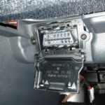
Connector Pin Orientation: Refer to the 4-pin connector diagram or the image below to ensure you insert the pins into the correct slots in the connector housing.
-
Insert Pins into Connector: Push each pin into its designated slot in the 4-pin connector from the rear until you hear a click. This click indicates that the pin is locked securely in place. Needle-nose pliers can be helpful to gently pull the wire from the front to ensure the pin is fully seated and locked.
- Pin 14 (brown w/white stripe) > Connector Slot A
- Pin 6 (green) > Connector Slot B
- Pin 16 (green w/white stripe) > Connector Slot C
- Pin 4 (orange) > Connector Slot D
Testing Your DIY OBD2 to USB Cable
Congratulations! You’ve built your Diy Obd2 To Usb Cable. Now it’s time to test it. Connect the OBD2 end to your car’s OBD2 port and the 4-pin connector end to a compatible USB adapter or interface that works with OBD2 software on your computer.
With the cable connected and software running, you should now be able to read diagnostic trouble codes (DTCs), clear codes, and access live data from your vehicle.
Final Note: If you encounter any issues or if any step is unclear, don’t hesitate to ask for clarification. Building this DIY OBD2 to USB cable is a rewarding project that provides a deeper understanding of your car’s systems and saves you money on professional diagnostic tools. Happy tinkering!

