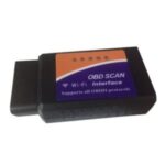
For automotive enthusiasts and DIY mechanics looking to delve into engine control unit (ECU) programming, also known as powertrain control module (PCM) programming, a reliable benchtop setup is crucial. The risk of battery issues or poor connections during live vehicle tuning can lead to corrupted flashes and damaged PCM modules. This guide outlines how to construct a robust PCM programming harness, incorporating a DB9 connector for OBD2 compatibility, ideal for bench tuning GM vehicles and others. While readily available OBD2 adapters exist, understanding how to integrate a DB9 connection for serial data communication into your harness provides valuable flexibility, especially when working with older and newer vehicle systems.
Why Build a PCM Programming Harness?
Bench tuning offers a safer and more controlled environment for reprogramming your vehicle’s PCM. By removing the PCM from the car and powering it externally, you eliminate the variables of vehicle battery voltage fluctuations and the risk of draining the car battery during lengthy programming sessions. This is particularly important when using software like TunerCat or LT1 Edit, which are popular in the GM tuning community. A dedicated harness ensures a stable power supply and consistent data connection, minimizing the chances of programming errors and potential PCM damage.
Components for Your Harness
To build this harness, you will need a few key components. While the original guide mentioned Radio Shack and Delphi, modern builders might consider sources like Amazon, Digi-Key, or Mouser for these parts. Fry’s Electronics, while once a popular source, is no longer operational, but the spirit of sourcing components for DIY projects remains. You’ll need:
- Power Supply: A stable 12V power supply is essential. The original guide used a Radio Shack power supply, but any regulated 12V supply capable of delivering a few amps will work. Look for one that outputs around 13.5V, as you’ll need to drop it slightly to a safer 12.6V for the PCM.
- Diodes: 1N4001 diodes (or similar) to reduce the voltage from the power supply. Two in series on the negative lead will drop the voltage appropriately.
- Connectors:
- PCM Connectors: You’ll need connectors that mate with your specific PCM. The original guide references color-coded connectors (BLUE, BLACK, GRAY, RED) which are specific to certain GM PCMs. Identify the correct connectors for your PCM.
- DB9 Connector: A female DB9 connector for OBD2 serial data communication. This is a key component for interfacing with OBD2 diagnostic and programming tools.
- DB25 Connector (Optional): A female DB25 connector for OBD1 compatibility, if you plan to work with older OBD1 systems. This adds versatility to your harness.
- Wiring: Automotive-grade wire in various colors to help keep your wiring organized.
- Budd Box (Project Enclosure): A small enclosure to house the wiring and an optional toggle switch.
- Toggle Switch (Optional): For switched +12V power, particularly important for OBD2 PCM safety.
Wiring the Harness: DB9 and OBD2 Integration
The core of the harness is the wiring. Here’s a breakdown of the connections, adapted from the original guide and focused on DB9 to OBD2 integration:
-
Power Supply Connection:
- Connect the positive (+) terminal of your power supply to the designated +12V pins on your PCM connectors. For example, on the BLUE connector, pin D3 (pink wire) and on the BLACK connector, pins B15 and B31 (orange wires) are +12V.
- Connect the negative (-) terminal of your power supply (after the diodes for voltage drop) to the GND (Ground) pins on the PCM connectors. For instance, BLUE connector D1 (black/white wire), GRAY connector C32 (black/white wire), and RED connector A18 and A2 (black/white wires) are grounds.
-
DB9 Connector (OBD2 Data):
- Pin 7 of the DB9 connector is for OBD2 Data. Connect this to the OBD-2 Serial Data pin on your PCM connector. In the example, this is BLUE connector pin D7 (purple wire).
- Pins 1 and 2 of the DB9 are Ground (GND). Connect these to a ground point in your harness, which is ultimately connected to the power supply’s negative terminal.
- Pin 9 of the DB9 is +12V. Connect this to a +12V source in your harness, derived from the power supply’s positive terminal.
-
DB25 Connector (OBD1 Data – Optional):
- Pin 5 of the DB25 connector is for OBD1 Data. Connect this to the OBD-1 Serial Data pin on your PCM connector. In the example, this is BLUE connector pin D30 (tan wire).
- Pin 1 of the DB25 is Ground (GND). Connect this to a ground point in your harness.
Caption: Example wiring setup for a PCM programming harness, highlighting the DB9 connector for OBD2 data.
- Switched +12V (OBD2 Safety):
- For OBD2 PCMs, a switched +12V line is crucial to prevent damage. The original guide uses BLACK connector pin B30 (pink wire) as a switched +12V. Wire this through a toggle switch in your Budd box. This line should be switched ON after the main power supply is connected for OBD2 PCMs. For OBD1, this line can be always-on.
Power Supply Considerations and Safety
Using a stable power supply is paramount. Ensure your power supply can maintain at least 12.5V under load. A UPS (Uninterruptible Power Supply) is a worthwhile investment to protect against power outages during programming, further safeguarding your PCM. Always double-check your wiring and pinouts before connecting to a PCM. Incorrect wiring can lead to irreversible damage. The toggle switch for the switched +12V line for OBD2 PCMs is not optional – it’s a critical safety measure.
Conclusion
Building a PCM programming harness with DB9 to OBD2 capability offers a safe and reliable method for bench tuning. While components can be sourced from various electronics suppliers, understanding the wiring and power requirements is key. This DIY approach empowers you to take control of your PCM programming, minimizing risks and maximizing flexibility for both OBD1 and OBD2 systems. Remember to always consult your vehicle’s service manual and PCM pinout diagrams specific to your application for accurate wiring.
