Want to dive deep into your vehicle’s real-time data?
This guide provides a comprehensive overview of OBD2 Mode 01, focusing on current data parameters. We’ll explore how to access and interpret this valuable information for vehicle diagnostics and performance monitoring.
Note: This is a detailed guide designed to help you understand and utilize OBD2 current data mode effectively for practical applications.
Discover why this is considered a top resource for understanding Current Data Mode Obd2.
You can also watch our OBD2 introduction video above – or download the PDF guide for offline access.
Understanding OBD2 Current Data Mode (Mode 01)
OBD2, or On-Board Diagnostics II, is a standardized system in modern vehicles that allows you to access a wealth of diagnostic information. At the heart of this system is the current data mode, also known as Mode 01. This mode is specifically designed to provide access to your vehicle’s real-time sensor data and operating parameters.
Have you ever seen the check engine light illuminate on your dashboard?
That’s your vehicle signaling a potential issue. Mechanics use OBD2 scanners to diagnose these problems, often starting with OBD2 current data mode.
By connecting an OBD2 scanner to the 16-pin OBD2 connector, typically located near the steering wheel, you can send requests to your car’s computer. The vehicle responds with data transmitted via current data mode OBD2, including parameters like engine speed, coolant temperature, and sensor readings. This real-time data stream is crucial for troubleshooting issues and understanding your vehicle’s performance.
A diagnostic scan tool displaying real-time parameters accessed through OBD2 current data mode, essential for automotive troubleshooting.
Is OBD2 Current Data Mode Available on My Vehicle?
Likely, yes!
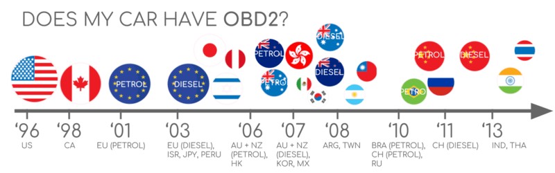
The vast majority of gasoline and diesel vehicles manufactured after the mid-1990s support OBD2, including current data mode. While older vehicles might have a 16-pin connector, it’s important to verify OBD2 compliance to ensure access to current data parameters. Compliance often depends on the vehicle’s manufacturing origin and year:
A chart illustrating OBD2 compliance timelines across different regions and vehicle types, helping determine if current data mode is supported.
The Evolution of OBD2 and Current Data Mode
OBD2’s origins trace back to California, driven by the California Air Resources Board (CARB) in the early 1990s for emissions monitoring. The Society of Automotive Engineers (SAE) played a key role in standardizing OBD2, including current data mode parameters and the diagnostic connector itself (SAE J1962).
The implementation of OBD2 and current data mode became progressively mandated:
- 1996: OBD2 mandated in the USA for cars and light trucks, including current data mode for emissions-related diagnostics.
- 2001: OBD2 required in the EU for gasoline vehicles, ensuring access to current data parameters.
- 2003: OBD2 extended to diesel vehicles in the EU (EOBD), further emphasizing current data monitoring.
- 2005: OBD2 became mandatory for medium-duty vehicles in the US, enhancing real-time data access across vehicle categories.
- 2008: US vehicles mandated to use ISO 15765-4 (CAN) as the communication protocol for OBD2, impacting how current data is transmitted.
- 2010: OBD2 extended to heavy-duty vehicles in the US, solidifying current data mode as a standard for vehicle diagnostics.
A visual representation of OBD2 history, highlighting the development and standardization of current data mode for emissions and diagnostics.
A timeline illustrating the historical milestones in OBD2 development, emphasizing the increasing importance of current data mode.
An illustration of OBD3 concepts, hinting at the future of remote diagnostics and enhanced current data monitoring capabilities.
The Future of OBD2 and Current Data Access
OBD2, including current data mode, is expected to remain a cornerstone of vehicle diagnostics. However, the automotive landscape is evolving, particularly with electric vehicles (EVs). Interestingly, most current EVs do not fully support standard OBD2 current data parameters. They often rely on manufacturer-specific UDS communication protocols, making current data access more challenging outside of official channels. Despite this, reverse engineering efforts are making headway in accessing data from EVs like Tesla, Hyundai/Kia, Nissan, and VW/Skoda.
Modern OBD alternatives like WWH-OBD and OBDonUDS are emerging to address limitations in data richness and communication protocols. These aim to improve OBD communication using the UDS protocol, offering potential enhancements to current data mode capabilities. Learn more about these protocols in our introduction to UDS.
The rise of connected cars is pushing for advancements beyond manual OBD2 checks. OBD3 concepts propose integrating telematics into vehicles, enabling remote current data monitoring and diagnostics. This involves incorporating radio transponders to transmit VIN and DTCs wirelessly for centralized analysis. While convenient and cost-effective, OBD3 raises privacy concerns, presenting a political and social challenge.
The automotive industry is also contemplating shifts in current data access. Historically intended for repair shops, OBD2’s current data mode is now widely used by third parties for various data-driven services. Some manufacturers propose restricting OBD2 access while driving, centralizing data collection instead. This could impact the third-party OBD2 service market, potentially limiting direct access to current data parameters. Security concerns, such as car hacking risks, are cited as reasons, though commercial motivations are also suspected. The future of current data access via OBD2 remains uncertain, potentially disrupting existing ecosystems.
An image symbolizing potential limitations on OBD2 access in electric vehicles, affecting the availability of current data parameters.
Enhance Your Vehicle Knowledge with Our ‘Ultimate CAN Guide’
Ready to become proficient in CAN bus and vehicle data analysis?
Our comprehensive 160+ page PDF guide offers 12 easy-to-understand introductions to CAN bus and related technologies:
Download the Ultimate CAN Guide Now
OBD2 Standards and Current Data Parameters
On-board diagnostics OBD2 operates as a higher-layer protocol, similar to a language, built upon communication methods like CAN bus, which acts as the communication channel. This structure parallels other CAN-based protocols like J1939, CANopen, and NMEA 2000.
OBD2 standards meticulously define aspects like the OBD2 connector, communication protocols, and crucially, OBD2 Parameter IDs (PIDs), which are central to current data mode.
These standards are often categorized within a 7-layer OSI model, with both SAE and ISO standards contributing to various layers. SAE standards are primarily US-centric, while ISO standards are more prevalent in Europe, resulting in some technically equivalent standards, such as SAE J1979 and ISO 15031-5 for diagnostic services, and SAE J1962 and ISO 15031-3 for the OBD connector.
An OSI model diagram illustrating the layers relevant to OBD2 and CAN bus standards, including those impacting current data transmission and interpretation.
A pinout diagram of the OBD2 connector, essential for physically accessing current data mode and other diagnostic services.
The OBD2 Connector: Your Gateway to Current Data [SAE J1962]
The 16-pin OBD2 connector, standardized under SAE J1962 / ISO 15031-3, is your physical interface for accessing vehicle data, including current data parameters. This Data Link Connector (DLC) is designed for easy access to diagnostic information.
Key points about the OBD2 connector:
- It’s typically located near the steering wheel, though its exact location can vary and may be somewhat hidden.
- Pin 16 provides battery power, often active even when the ignition is off, enabling continuous monitoring in some applications.
- The OBD2 pinout configuration is protocol-dependent.
- CAN bus, the most prevalent lower-layer protocol, commonly utilizes pins 6 (CAN-H) and 14 (CAN-L) for communication, including current data transmission.
OBD2 Connector Types: Type A vs. Type B
You might encounter both Type A and Type B OBD2 connectors. Type A is standard in cars, while Type B is more common in medium and heavy-duty vehicles.
While both types share similar pinouts, Type A provides 12V power, and Type B offers 24V. Baud rates can also differ; cars usually use 500K, while heavy-duty vehicles often use 250K (with increasing support for 500K).
Type B connectors feature an interrupted groove, making Type B OBD2 adapter cables compatible with both Type A and Type B sockets. However, Type A adapters are not compatible with Type B sockets.
A comparison of OBD2 connector types A and B, highlighting differences in power supply and physical compatibility, relevant for current data retrieval in different vehicle types.
A diagram depicting the relationship between OBD2 and CAN bus, emphasizing CAN bus as the communication layer for OBD2 current data transmission.
OBD2 and CAN Bus: The Protocol for Current Data [ISO 15765-4]
Since 2008, CAN bus (ISO 15765) has been the mandatory lower-layer protocol for OBD2 in US vehicles, influencing how current data mode operates.
ISO 15765-4, also known as Diagnostics over CAN (DoCAN), specifies how OBD2 functions over CAN (ISO 11898). It standardizes the CAN interface for diagnostic tools, focusing on the physical, data link, and network layers, all crucial for reliable current data retrieval.
Key specifications of ISO 15765-4 for current data communication:
- CAN bus bit-rate must be 250K or 500K.
- CAN IDs can be 11-bit or 29-bit.
- Specific CAN IDs are designated for OBD requests and responses, including those for current data parameters.
- Diagnostic CAN frame data length is fixed at 8 bytes, affecting the structure of current data messages.
- The OBD2 adapter cable length is limited to 5 meters.
OBD2 CAN Identifiers: Requesting and Receiving Current Data (11-bit, 29-bit)
OBD2 communication, including current data requests, is based on request/response message pairs.
Most vehicles use 11-bit CAN IDs for OBD2. Functional Addressing, using ID 0x7DF, broadcasts a request to all OBD2-compatible ECUs, asking if they have data for the requested parameter. Physical Addressing, using IDs 0x7E0-0x7E7, targets specific ECUs, though it’s less common for current data requests.
ECUs respond with 11-bit IDs in the range 0x7E8-0x7EF. The most common response ID is 0x7E8 (ECM, Engine Control Module), often providing current data parameters related to engine functions, and 0x7E9 (TCM, Transmission Control Module).
Some vehicles, particularly vans and medium/heavy-duty vehicles, may use extended 29-bit CAN identifiers for OBD2 communication, including current data exchange.
In 29-bit CAN, Functional Addressing uses ID 0x18DB33F1. Responses are typically in the range 0x18DAF100 to 0x18DAF1FF (often 18DAF110 and 18DAF11E). The response ID is sometimes represented in J1939 PGN format, specifically PGN 0xDA00 (55808), which is reserved for ISO 15765-2 in the J1939-71 standard.
Diagram illustrating the structure of OBD2 request and response frames, crucial for understanding how current data parameters are exchanged.
A visual comparison of OBD2 and proprietary CAN bus protocols, highlighting the difference between standardized current data and manufacturer-specific data streams.
OBD2 vs. Proprietary CAN Protocols: Understanding Data Access Limits
It’s crucial to understand that vehicle ECUs primarily operate using OEM-specific CAN protocols, not OBD2. OBD2, including current data mode, is an additional protocol implemented for diagnostics and standardized data access. OEM-specific CAN protocols are unique to each manufacturer, vehicle model, and year. Interpreting this proprietary data is generally not possible without OEM documentation or reverse engineering.
Connecting a CAN bus data logger to your OBD2 port might capture OEM-specific CAN data, often broadcast at high rates. However, many newer vehicles employ a ‘gateway’ that restricts OBD2 port access to OBD2 communication only, blocking OEM-specific data.
Think of OBD2, and current data mode in particular, as a standardized, parallel protocol existing alongside the OEM-specific protocols that govern vehicle operation.
Bit-rate and ID Validation: Ensuring Correct Current Data Communication
OBD2 can use two bit-rates (250K, 500K) and two CAN ID lengths (11-bit, 29-bit), resulting in four potential combinations. Modern vehicles commonly use 500K and 11-bit IDs, but diagnostic tools should systematically validate these settings.
ISO 15765-4 provides a validation sequence to determine the correct combination. This process leverages the fact that OBD2-compliant vehicles must respond to a mandatory OBD2 request (see OBD2 PID section) and that incorrect bit-rates lead to CAN error frames.
Newer ISO 15765-4 versions account for OBD communication via OBDonUDS as well as OBDonEDS. This article primarily focuses on OBDonEDS (OBD on Emission Diagnostic Service), which is widely used in non-EVs today. WWH-OBD/OBDonUDS is more common in EU trucks and buses.
To differentiate between OBDonEDS and OBDonUDS, diagnostic tools can send UDS requests with specific IDs for service 0x22 and DID 0xF810 (protocol identification). Vehicles supporting OBDonUDS should respond to this DID.
OBDonEDS (also termed OBD2, SAE OBD, EOBD, or ISO OBD) is prevalent in most current non-electric vehicles, while WWH-OBD is primarily used in European trucks and buses.
A flowchart illustrating the process of validating OBD2 bit-rate and CAN ID settings, ensuring proper communication for current data retrieval.
A diagram showing the five lower-layer OBD2 protocols, including CAN (ISO 15765), KWP2000, SAE J1850, and ISO 9141, reflecting historical and current communication methods.
Five Lower-Layer OBD2 Protocols: A Historical Perspective
While CAN (ISO 15765) is dominant today, older vehicles (pre-2008) may use one of four other lower-layer protocols for OBD2, influencing current data transmission methods. Understanding these protocols and their pinouts can be helpful for diagnosing older vehicles:
- ISO 15765 (CAN bus): Mandatory in US cars since 2008 and now the most common for current data and diagnostics.
- ISO14230-4 (KWP2000): Keyword Protocol 2000, used in 2003+ vehicles, especially in Asia.
- ISO 9141-2: Used in EU, Chrysler, and Asian vehicles in 2000-04.
- SAE J1850 (VPW): Predominantly used in older GM vehicles.
- SAE J1850 (PWM): Predominantly used in older Ford vehicles.
ISO-TP: Transporting OBD2 Messages for Current Data and Beyond [ISO 15765-2]
OBD2 data, including current data parameters, is transmitted over CAN bus using ISO-TP (ISO 15765-2), a transport protocol that allows for payloads exceeding 8 bytes. This is essential for OBD2 functions like retrieving VIN or DTCs, which require more data than a single CAN frame can hold. ISO 15765-2 manages segmentation, flow control, and reassembly of these larger messages. For more details, see our introduction to UDS.
However, much of the current data accessed in Mode 01 fits within a single CAN frame. In these cases, ISO 15765-2 specifies ‘Single Frame’ (SF) usage. The first data byte (PCI field) indicates payload length (excluding padding), leaving 7 bytes for OBD2-related communication, suitable for many current data parameters.
Diagram illustrating the different frame types defined in ISO 15765-2 for ISO-TP, including Single Frame for short messages and multi-frame types for larger OBD2 data like VIN or DTCs.
The OBD2 Diagnostic Message Structure: Deconstructing Current Data [SAE J1979, ISO 15031-5]
To understand OBD2 communication on CAN, consider a ‘Single Frame’ OBD2 CAN message. An OBD2 message comprises an identifier, data length (PCI field), and data. The data section is further divided into Mode, Parameter ID (PID), and data bytes. This structure is consistent for current data mode and other OBD2 services.
Breakdown of an OBD2 message structure, showing the arrangement of Mode, Parameter ID (PID), and data bytes within a CAN frame, essential for interpreting current data parameters.
Example: OBD2 Request/Response for Current Data
Let’s examine a request/response example for ‘Vehicle Speed’, a common current data parameter.
A diagnostic tool sends a request to the vehicle with CAN ID 0x7DF and 2 payload bytes: Mode 0x01 and PID 0x0D. The vehicle responds with CAN ID 0x7E8 and 3 payload bytes, including the Vehicle Speed value in the 4th byte, 0x32 (decimal 50).
Using OBD2 PID decoding rules, 0x32 corresponds to 50 km/h for Vehicle Speed. This illustrates how current data parameters are requested and interpreted.
Example of an OBD2 request and response sequence for Vehicle Speed, demonstrating how current data parameters are requested and received.
Detailed example of OBD2 PID 0D (Vehicle Speed), illustrating the PID value and its interpretation into a physical unit (km/h).
Overview of the 10 OBD2 service modes, highlighting Current Data (Mode 01) along with other diagnostic services like Freeze Frame and Clear DTCs.
The 10 OBD2 Services (Modes): Accessing Current Data and Diagnostics
OBD2 defines 10 diagnostic services, or modes. Mode 0x01, current data mode, provides real-time data parameters. Other modes are used for diagnostic trouble codes (DTCs) and freeze frame data.
Vehicles aren’t required to support all OBD2 modes and may also implement OEM-specific modes beyond the 10 standard ones.
In OBD2 messages, the mode is in the second byte. In requests, the mode is directly included (e.g., 0x01). In responses, 0x40 is added to the mode value (e.g., resulting in 0x41 for Mode 01 responses).
OBD2 Parameter IDs (PIDs): Identifying Current Data Signals
Each OBD2 mode contains Parameter IDs (PIDs).
Mode 0x01 (current data mode) includes approximately 200 standardized PIDs for real-time data such as speed, RPM, and fuel level. However, vehicles typically support a subset of these PIDs.
PID 0x00 within Mode 0x01 is special. If an emissions-related ECU supports any OBD2 services, it must support Mode 0x01 PID 0x00. Responding to this PID, the ECU indicates support for PIDs 0x01-0x20. This makes PID 0x00 a fundamental OBD2 compatibility test. PIDs 0x20, 0x40, and so on, similarly indicate support for subsequent PID ranges within Mode 0x01.
Reiteration of the OBD2 request and response frame structure, emphasizing the role of PIDs in specifying current data parameters.
Screenshot of an OBD2 PID overview tool, showcasing its utility in exploring and understanding available current data parameters in Mode 01.
Tip: OBD2 PID Overview Tool for Current Data Exploration
SAE J1979 and ISO 15031-5 appendices detail scaling information for standard OBD2 PIDs, enabling conversion of raw data to physical values.
Our OBD2 PID overview tool is a helpful resource for Mode 0x01 PIDs. It assists in constructing OBD2 request frames and dynamically decoding responses, simplifying current data parameter interpretation.
Access the OBD2 PID Overview Tool
Logging and Decoding OBD2 Current Data: A Practical Guide
This section provides a practical guide on logging OBD2 current data using a CANedge CAN bus data logger.
The CANedge can be configured to transmit custom CAN frames for OBD2 requests, making it suitable for current data logging.
Connect the CANedge to your vehicle using an OBD2-DB9 adapter cable for easy current data capture.
Diagram showing an OBD2 data logger requesting current data parameters using CAN IDs 7DF and 7E8 for communication.
Screenshot from asammdf software showing responses to ‘Supported PIDs’ requests, used to identify available current data parameters.
Step #1: Bit-rate, ID, and Supported PID Validation for Current Data
ISO 15765-4 outlines how to determine the bit-rate and IDs for a specific vehicle. The CANedge can perform these tests:
- Test at 500K bit-rate; if successful, proceed. Otherwise, try 250K.
- Use the verified bit-rate for subsequent communication.
- Send ‘Supported PIDs’ requests and analyze responses to identify available current data parameters.
- Response IDs indicate 11-bit or 29-bit CAN ID usage.
- Response data reveals supported PIDs for current data mode.
We offer plug-and-play configurations to simplify these tests.
Most post-2008 non-EVs support 40-80 PIDs, using 500K bit-rate, 11-bit CAN IDs, and the OBD2/OBDonEDS protocol for current data access.
As shown in the asammdf GUI screenshot, multiple responses to a single OBD request are common due to the 0x7DF request ID, which polls all ECUs. Since all OBD2/OBDonEDS-compliant ECUs must support service 0x01 PID 0x00, numerous responses to this PID are typical. Subsequent ‘Supported PIDs’ requests receive fewer responses as fewer ECUs support those PIDs. The ECM ECU (0x7E8) often supports all PIDs supported by other ECUs in this example, suggesting that bus load can be reduced by directing requests specifically to this ECU using Physical Addressing CAN ID 0x7E0 for subsequent current data queries.
Step #2: Configuring OBD2 PID Requests for Current Data Logging
Once you know your vehicle’s supported PIDs, bit-rate, and CAN IDs, you can configure your logging setup to request specific current data parameters.
Consider these factors when configuring your requests:
- CAN IDs: Use ‘Physical Addressing’ request IDs (e.g., 0x7E0) to avoid multiple responses and streamline current data acquisition.
- Spacing: Add 300-500 ms intervals between OBD2 requests to prevent ECU overload and ensure reliable responses for current data.
- Battery Drain: Implement triggers to stop transmissions when the vehicle is inactive, preventing ECU ‘wake-up’ and battery drain during current data logging.
- Filters: Filter to record only OBD2 responses, especially if OEM-specific CAN data is also present, to focus on relevant current data streams.
With these settings, your logger is ready to record raw OBD2 current data!
Example of a CANedge OBD2 PID request list, configured to retrieve specific current data parameters from a vehicle.
Screenshot from asammdf showing decoded and visualized OBD2 data, demonstrating how current data parameters can be plotted and analyzed.
Step #3: DBC Decoding of Raw OBD2 Current Data
To analyze and visualize your logged data, decode the raw OBD2 data into physical values.
Decoding information is in ISO 15031-5/SAE J1979 and online resources. We provide a free OBD2 DBC file to simplify DBC decoding in CAN bus software tools.
Decoding OBD2 current data is more complex than standard CAN signals. Different OBD2 PIDs share CAN IDs (e.g., 0x7E8), so the CAN ID alone isn’t enough to identify the signals.
You must use the CAN ID, OBD2 mode, and OBD2 PID together for signal identification. This ‘extended multiplexing’ method is supported in DBC files.
CANedge: Your OBD2 Current Data Logger
The CANedge enables easy recording of OBD2 current data to SD cards (8-32 GB). Connect it to your vehicle to start logging and use free software/APIs and our OBD2 DBC for data decoding.
OBD2 Logger Introduction Explore CANedge
OBD2 Multi-Frame Examples: VIN, Multi-PID Requests, and DTCs
OBD2 communication uses ISO-TP (ISO 15765-2). Most examples so far are single-frame. This section covers multi-frame communication examples.
Multi-frame OBD2 requires flow control frames. In practice, transmitting a static flow control frame ~50 ms after the initial request works, as shown in the CANedge configuration example.
Multi-frame OBD2 responses need CAN software/API tools supporting ISO-TP, like CANedge MF4 decoders.
Example of an OBD2 multi-frame request message used to retrieve the Vehicle Identification Number (VIN), demonstrating ISO-TP in action.
Example 1: OBD2 Vehicle Identification Number (VIN) Retrieval
The Vehicle Identification Number (VIN) is important for telematics and diagnostics. Retrieve it via OBD2 using mode 0x09 and PID 0x02:
The tool sends a Single Frame request with PCI (0x02), service ID (0x09), and PID (0x02).
The vehicle responds with a First Frame containing PCI, length (0x014 = 20 bytes), mode (0x49), and PID (0x02). Byte 0x01 is the Number Of Data Items (NODI), here 1. The remaining 17 bytes are the VIN, convertible from HEX to ASCII.
Example 2: OBD2 Multi-PID Request (6x)
Tools can request up to 6 Mode 0x01 OBD2 PIDs in a single request frame. The ECU responds with data for supported PIDs, using multi-frame responses if needed.
This increases data collection efficiency but complicates signal encoding, making generic OBD2 DBC files less useful. We don’t generally recommend this method. Below is an example trace:
The multi-frame response is similar to the VIN example, but the payload includes requested PIDs and their data. PIDs are often ordered as requested.
Decoding this via DBC files is complex, and we advise against this approach for general data logging unless using tools with specific support. It involves extended multiplexing, with payload positions varying by PID, making DBC generalization difficult. Handling multiple multi-PID requests further complicates DBC management.
Custom scripts and recording request messages can help, allowing interpretation based on request-response pairs, but these are hard to scale.
Example 3: OBD2 Diagnostic Trouble Codes (DTCs) Retrieval
Use OBD2 mode 0x03 (‘Show stored Diagnostic Trouble Codes’) to request emissions-related DTCs. No PID is needed in the request. ECUs respond with the number of stored DTCs (possibly 0), each DTC using 2 data bytes, often requiring multi-frame responses for more than 2 DTCs.
The 2-byte DTC value is split into category and a 4-digit hexadecimal code, as per ISO 15031-5/ISO 15031-6. Decode DTC values using OBD2 DTC lookup tools like repairpal.com.
The example below shows a request to an ECU with 6 DTCs.
Diagram illustrating how OBD2 Diagnostic Trouble Codes (DTCs) are decoded, showing the category and 4-digit code structure within the 2-byte DTC value.
OBD2 Data Logging: Use Case Examples
OBD2 data logging from cars and light trucks has diverse applications:
Car Data Logging
OBD2 data helps reduce fuel costs, improve driving habits, test prototype parts, and optimize insurance models.
Explore OBD2 Loggers
Real-time Car Diagnostics
OBD2 interfaces stream human-readable data for real-time vehicle issue diagnosis.
Discover OBD2 Streaming Interfaces
Predictive Maintenance
IoT OBD2 loggers monitor vehicles in the cloud to predict and prevent breakdowns.
Learn about Predictive Maintenance Solutions
Vehicle Blackbox Logger
OBD2 loggers serve as ‘black boxes’ for vehicles, providing data for disputes and diagnostics.
Explore CAN Bus Blackbox Loggers
Have an OBD2 data logging use case? Contact us for free consultation!
Contact Us for Expert Advice
For more guides, see our tutorials section or download the ‘Ultimate Guide’ PDF.
Need to log/stream OBD2 data?
Get your OBD2 data logger today!
Buy Now: OBD2 Data Loggers Contact Us for Support
Recommended for You
OBD2 DATA LOGGER: EASILY LOG & CONVERT OBD2 DATA
CANEDGE2 – PRO CAN IoT LOGGER
[