Diagnosing your car’s problems often begins with plugging in an OBD2 scanner. This handy tool reads data from your vehicle’s computer, helping to identify issues quickly. But what if you plug in your scanner and nothing happens? A “car PCM won’t connect to OBD2 scanner” issue can be frustrating, leaving you in the dark about your vehicle’s health.
This guide will walk you through the common reasons why your OBD2 scanner might fail to connect to your car’s Powertrain Control Module (PCM), and provide troubleshooting steps to get you back on track.
Common Reasons Why Your OBD2 Scanner Isn’t Connecting
Several factors can prevent your OBD2 scanner from communicating with your car’s PCM. Understanding these potential issues is the first step in diagnosing the problem:
-
Faulty OBD2 Scanner: The simplest explanation is that your scanner itself is malfunctioning. Like any electronic device, OBD2 scanners can experience hardware or software failures. Before assuming a complex car issue, test your scanner on another vehicle if possible.
-
Damaged OBD2 Port: The OBD2 port in your car, also known as the Diagnostic Link Connector (DLC), can be physically damaged. Check for bent or broken pins, debris, or corrosion inside the port. Damage here can interrupt the connection needed for data transfer.
-
Wiring Issues: The OBD2 port isn’t directly connected to the PCM wirelessly. Wires link the port to the vehicle’s computer system. If these wires are damaged, disconnected, or corroded, communication will be impossible. This is a more intricate issue requiring careful inspection.
-
PCM Problems: While less common, the PCM itself could be the source of the problem. If the PCM has internal faults or isn’t powered correctly, it won’t respond to the OBD2 scanner’s requests. This is a more serious issue that might require professional diagnosis.
-
Power Supply Problems: The PCM and OBD2 port need power to function. A dead or weak car battery can prevent the scanner from establishing a connection. Similarly, a blown fuse in the circuit supplying power to the OBD2 port or PCM can also be the culprit.
Troubleshooting Steps to Diagnose OBD2 Connection Issues
If your car PCM won’t connect to the OBD2 scanner, follow these troubleshooting steps. You’ll need a Digital Multimeter (DMM) for voltage testing.
Preliminary Checks
- Verify Scanner Function: Try your OBD2 scanner on a different vehicle to confirm it’s working correctly. If it fails to connect to another car, the scanner is likely faulty.
- Inspect the OBD2 Port: Visually examine your car’s OBD2 port for any physical damage, bent pins, or obstructions. A flashlight can be helpful here.
Voltage Tests at the OBD2 Port
These tests require a DMM and will help you pinpoint power and ground issues at the OBD2 port.
Test 1: Ground Circuit Check (Pin 4)
-
Set your DMM to measure DC Volts.
-
Locate pin 4 on your OBD2 port (refer to an OBD2 pinout diagram if needed – often available online).
-
Connect the positive (red) lead of your DMM to pin 4.
-
Connect the negative (black) lead of your DMM directly to the negative terminal of your car battery. Do not connect to chassis ground. Use jumper wires if needed to reach the battery terminal.
-
Turn the ignition key to the “ON” position (engine off).
-
Observe the voltage reading on your DMM.
- Expected Result: The voltage drop should be 0.1 Volts or less.
- Problem Indicated: A higher voltage reading suggests high resistance or an open circuit in the ground connection of pin 4.
Test 2: Ground Circuit Check (Pin 5)
-
Repeat Test 1, but connect the positive DMM lead to pin 5 of the OBD2 port instead of pin 4.
- Expected Result: Again, the voltage drop should be 0.1 Volts or less.
- Problem Indicated: A high voltage reading on pin 5 also points to a ground circuit issue.
Note: If both ground circuit tests fail (high voltage readings), the PCM is unlikely to enter diagnostic mode, preventing scanner communication.
Test 3: PCM Data Transmission Check (Pin 2 – SAE J1850 PWM/VPW)
- Note: Pin 2 is for specific communication protocols (SAE J1850 PWM/VPW) and may not apply to all vehicles, particularly those using CAN protocol on pins 6 & 14. Consult your vehicle’s service manual or OBD2 pinout for your car. This test may not be applicable to Mazda MPV and vehicles using CAN on different pins.
-
Locate pin 2 on the OBD2 port.
-
Connect the positive (red) lead of your DMM to pin 2.
-
Connect the negative (black) lead of your DMM to a known good ground, which can be pin 4, pin 5, or the negative battery terminal.
-
Turn the ignition key to the “ON” position (engine off).
-
Observe the voltage reading.
- Expected Result: The voltage should be approximately 5V or fluctuate between 3.5V and 5.0V.
- Problem Indicated: If the voltage is significantly different or absent, it suggests the PCM is not transmitting data on this pin, possibly due to a PCM fault or wiring issue.
Test 4: Power Supply to OBD2 Port (Pin 16)
-
Locate pin 16 on the OBD2 port (this is typically the battery positive pin).
-
Connect the positive (red) lead of your DMM to pin 16.
-
Connect the negative (black) lead of your DMM to the negative terminal of the car battery.
-
Turn the ignition key to the “ON” position (or “ACC”).
-
Observe the voltage reading.
- Expected Result: You should read battery voltage (approximately 12V-14V when the car is off, may be slightly higher if the engine is running).
- Problem Indicated: No voltage or very low voltage indicates a lack of power to the OBD2 port. Check the fuse box for a blown fuse related to the cigarette lighter or auxiliary power outlets, as these circuits often power the OBD2 port.
Test 5: Bus Line Bias Voltage (Pins 6 & 14 – CAN High & CAN Low)
- Note: This test is relevant for vehicles using the CAN (Controller Area Network) protocol, which is common in modern cars. Pins 6 and 14 are typically used for CAN High and CAN Low respectively. Refer to your vehicle’s specific OBD2 pinout.
-
Locate pins 6 and 14 (or the bias terminals as per your vehicle’s wiring diagram).
-
Connect the positive (red) lead of your DMM to either pin 6 or 14 (test each pin separately).
-
Connect the negative (black) lead of your DMM to a known good ground.
-
Turn the ignition key to the “ON” position (engine off).
-
Observe the voltage reading for each pin.
- Expected Result (No Bus Activity): With ignition ON but no active communication, one pin (CAN High) should read approximately 0V, and the other (CAN Low) should read approximately 5V.
- Expected Result (Bus Activity): When the system is active, the voltage on both pins should vary between 0V and 5V, indicating data transmission.
- Problem Indicated: Incorrect or no voltage readings on these pins suggest issues with the CAN bus communication, potentially related to the PCM, wiring, or other modules on the network.
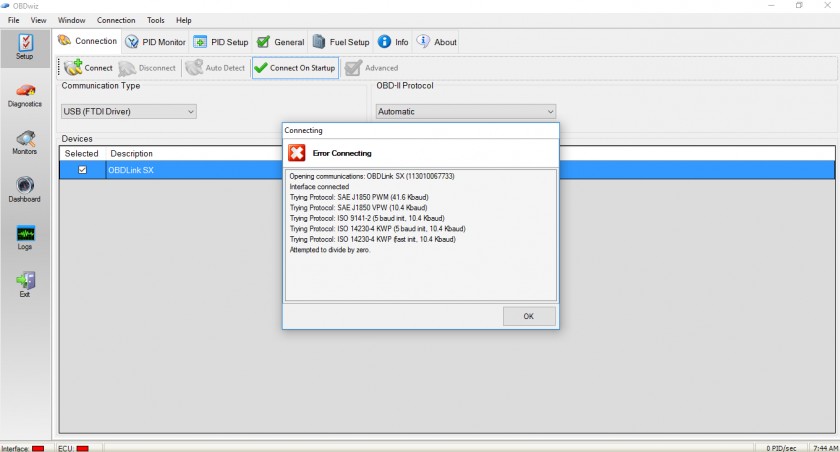
Image: An example of a PCM connection attempt failure. A faulty PCM or wiring issue can prevent successful communication with an OBD2 scanner.
When to Seek Professional Help
If you’ve performed these troubleshooting steps and are still facing a “car PCM won’t connect to OBD2 scanner” problem, it’s time to consider professional help. PCM and wiring issues can be complex and require specialized diagnostic tools and expertise. A qualified mechanic can further diagnose the problem, potentially involving more advanced scans and component testing to pinpoint the exact cause and perform necessary repairs.
By systematically checking these potential causes, you can significantly narrow down why your OBD2 scanner is failing to connect, and take appropriate steps towards resolving the issue and getting your car diagnosed.