The On-Board Diagnostics II (OBD2) system is your car’s built-in health monitor. Using an OBD2 scanner is often the first step for mechanics and car owners alike to diagnose a Check Engine Light or other performance issues. This handy tool plugs into your vehicle’s OBD2 port and reads diagnostic trouble codes (DTCs) from the car’s computer, offering valuable insights into what might be wrong.
However, frustration hits when you plug in your scanner and it simply won’t communicate with your vehicle. If you’re facing this problem, you’re not alone. This guide will walk you through the common reasons why your OBD2 scanner might fail to connect and provide troubleshooting steps to get you back on track to diagnosing your car problems.
Decoding OBD2 Communication Issues: Possible Causes
Several factors can prevent your OBD2 scanner from establishing a connection with your vehicle’s computer. Let’s explore the most frequent culprits:
-
Faulty OBD2 Scanner: Like any electronic device, your OBD2 scanner can malfunction. Internal hardware or software glitches can render it unable to communicate. Before assuming vehicle issues, rule out the scanner itself as the source of the problem.
-
Damaged or Defective OBD2 Port: The OBD2 port in your car, also known as the Diagnostic Link Connector (DLC), is your scanner’s gateway to your vehicle’s computer. This port can suffer physical damage, corrosion, or bent pins. A damaged port can disrupt the connection and prevent communication.
-
Wiring and Circuit Problems: The OBD2 port isn’t directly connected to the car’s computer magically. Wires link the port to the vehicle’s central processing unit, often the Powertrain Control Module (PCM) or Engine Control Module (ECM). Damaged, disconnected, or shorted wires in this circuit will obviously break the communication pathway. Furthermore, blown fuses in the OBD2 circuit can cut off power supply, leading to communication failure.
-
Vehicle Computer Issues (PCM/ECM): In rarer cases, the problem might lie within your vehicle’s computer itself. If the PCM or ECM has internal faults, it may not respond to the OBD2 scanner’s requests. While less common than port or wiring issues, a malfunctioning computer is a serious possibility.
-
Dead or Weak Car Battery: The OBD2 system relies on a stable power supply from your car battery. A completely dead battery will prevent any electrical systems, including the OBD2 port and vehicle computer, from functioning. Even a weak battery with insufficient voltage can sometimes cause communication problems.
Step-by-Step Troubleshooting When Your OBD2 Scanner Won’t Connect
When faced with an OBD2 scanner communication failure, systematic troubleshooting is key. Here are diagnostic tests you can perform using a Digital Multimeter (DMM) to pinpoint the problem. Safety First: Always consult your vehicle’s service manual and take necessary safety precautions when working with automotive electrical systems.
TEST 1: Ground Circuit Integrity Check (DLC Pin 4)
This test verifies the ground connection for the OBD2 port.
- Setup: Set your DMM to measure DC Voltage. Connect the positive (red) lead of your DMM to DLC pin 4 (ground pin). Connect the negative (black) lead directly to the negative terminal of your car battery. Important: Do not connect to chassis ground; connect directly to the battery terminal for accurate readings. Use jumper wires if needed to reach the battery terminal comfortably.
- Procedure: Turn the ignition key to the “ON” position (engine off).
- Reading: Observe the voltage reading on the DMM.
- Expected Result: The voltage drop should be very minimal, ideally 0.1 Volts or less.
- Interpretation: A reading significantly higher than 0.1V indicates excessive resistance in the ground circuit, possibly due to corrosion, loose connections, or wiring damage.
TEST 2: Ground Circuit Integrity Check (DLC Pin 5)
Repeat the exact procedure as TEST 1, but connect the positive DMM lead to DLC pin 5 (signal ground pin) instead of pin 4. The expected result and interpretation are the same as TEST 1.
Note: High ground resistance or an open ground circuit on pins 4 or 5 will prevent the PCM from entering diagnostic mode, thus blocking OBD2 communication.
TEST 3: Data Line Voltage Check (DLC Pin 2 – SAE J1850 PWM/VPW)
This test checks the voltage on the data communication line. Note: Pin 2 is specific to SAE J1850 PWM/VPW communication protocols, commonly found in older Ford and GM vehicles. It might not apply to all vehicles (e.g., not applicable to Mazda MPV as mentioned in the original text, and may not be relevant for CAN protocol vehicles on pin 2). Consult your vehicle’s wiring diagram to identify the correct data pins for your specific vehicle and protocol. Modern vehicles predominantly use CAN protocol, often on pins 6 and 14.
- Setup: Set your DMM to measure DC Voltage. Connect the positive (red) lead to DLC pin 2 (or the appropriate data pin for your vehicle’s protocol). Connect the negative (black) lead to a known good ground – you can use DLC pin 4 or 5, or a reliable chassis ground point.
- Procedure: Turn the ignition key to the “ON” position (engine off).
- Reading: Observe the voltage reading on the DMM.
- Expected Result: For a functional data line with J1850 PWM/VPW, you should typically see approximately 5V, or a fluctuating voltage between 3.5V and 5.0V, indicating data transmission activity.
- Interpretation: A steady reading of 0V on the data pin suggests an open circuit in the data line, meaning the PCM is unable to transmit data to the scan tool.
TEST 4: Power Supply Voltage Check (DLC Pin 16)
This test verifies that the OBD2 port is receiving power from the vehicle’s battery.
- Setup: Set your DMM to measure DC Voltage. Connect the positive (red) lead to DLC pin 16 (battery positive voltage pin). Connect the negative (black) lead to a known good ground (DLC pin 4 or 5, or battery negative terminal).
- Procedure: Turn the ignition key to the “ON” position (engine off).
- Reading: Observe the voltage reading on the DMM.
- Expected Result: You should read approximately the battery voltage (typically 12V-14.5V depending on battery charge and vehicle state).
- Interpretation: No voltage or significantly low voltage reading indicates a lack of power supply to the OBD2 port. This is often caused by a blown fuse in the circuit that powers the DLC, such as a lighter fuse or a dedicated diagnostic fuse. Check your vehicle’s fuse box diagram to identify and inspect the relevant fuse.
TEST 5: Bias Voltage Check (DLC Pins – Protocol Specific)
This test is more advanced and protocol-dependent. For CAN (Controller Area Network) protocol, commonly used in modern vehicles, you would typically check bias voltage on pins 6 (CAN High) and 14 (CAN Low). For ISO 9141-2 or KWP2000 protocols (ISO 14230), you might check pin 7 (K-line) and potentially pin 15 (L-line, if used). Consult your vehicle’s service information for the correct pins and expected bias voltage readings for your specific vehicle and communication protocol.
For a generalized example using CAN protocol (pins 6 and 14):
- Setup: Set your DMM to measure DC Voltage. Connect the positive (red) lead to DLC pin 6 (CAN High). Connect the negative (black) lead to a known good ground.
- Procedure: Turn the ignition key to the “ON” position (engine off).
- Reading and Expected Result (No Bus Activity): With ignition ON and no active communication on the CAN bus, you might expect to see approximately 2.5V on both CAN High and CAN Low pins relative to ground. The voltage difference between CAN High and CAN Low should be approximately 0V in a resting state.
- Reading and Expected Result (Bus Activity): When the system is active, the voltage on CAN High should fluctuate above 2.5V, and CAN Low should fluctuate below 2.5V. The voltage difference between CAN High and CAN Low will vary depending on the data being transmitted.
- Interpretation: Incorrect or absent bias voltages, or lack of voltage fluctuation during expected bus activity, can indicate problems with the CAN bus system, transceivers, or termination resistors, potentially within the PCM or other modules on the network. This often requires more advanced diagnostics.
Advanced Issues: PCM/ECM Failure and Fuse Box Problems
If the above tests don’t reveal obvious wiring or power supply issues, and you’ve ruled out a faulty scanner, the problem might be more complex. As highlighted in the original article, a failing or “fried” PCM/ECM can also be the reason for communication failure.
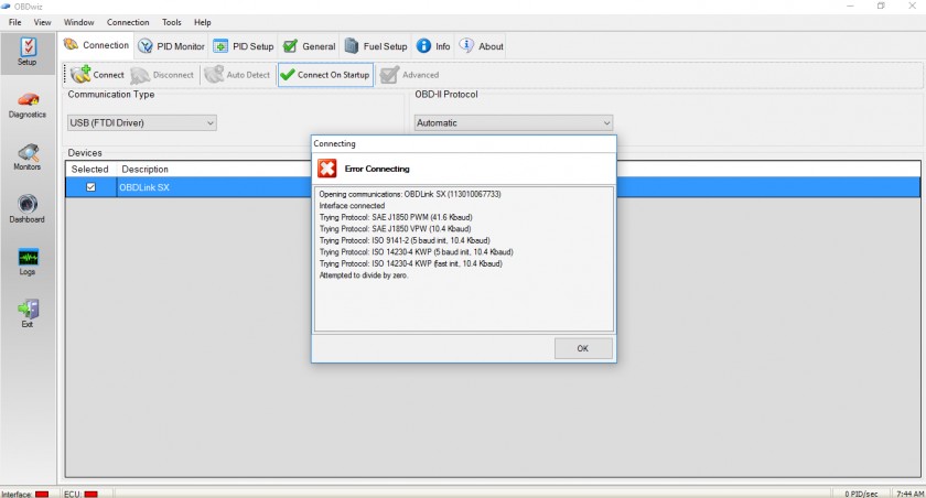 OBD2 Scanner Failed to Communicate with PCM: Error message displayed on scan tool after wiring repair, indicating potential PCM issue despite wiring fix attempt.
The image above illustrates an OBD2 scanner failing to communicate even after wiring repairs, suggesting a potential PCM issue. As noted, ensure the PCM is receiving proper power and ground. Referencing resources like FS1 Inc’s guide on diagnosing PCM issues can provide further insights into PCM power supply checks.
Moreover, thoroughly inspect your vehicle’s fuse box (power panel). A seemingly unrelated fuse could be linked to the PCM’s power or the OBD2 communication circuit. Always consult your vehicle’s wiring diagrams and service information for accurate fuse and circuit identification.
Conclusion: Systematic Troubleshooting is Key to OBD2 Communication Success
When your OBD2 scanner refuses to communicate, don’t panic. Start with the basics: check your scanner on another vehicle if possible, inspect the OBD2 port for damage, and then systematically work through the electrical tests outlined above. By methodically checking power, ground, and data circuits, you can often pinpoint the cause of the “can’t communicate with OBD2” issue and take steps towards resolving it, whether it’s a simple fuse replacement or addressing a more complex wiring problem. Remember to consult your vehicle-specific repair information for accurate procedures and specifications, and when in doubt, seek professional automotive diagnostic assistance.