As a proud owner of a used 2008 Can-Am Spyder GS, I’ve come to appreciate the unique blend of open-air freedom and added stability it offers compared to traditional motorcycles. My decision to purchase the Spyder was largely influenced by my wife’s peace of mind after a previous motorcycle mishap. The Spyder, with its three wheels, substantial road presence, and advanced anti-lock braking system, seemed like the perfect compromise. It allowed me to enjoy the road while keeping my wife, and myself, feeling secure.
However, beneath the surface of this technologically advanced machine lies a diagnostic system that has proven to be a source of frustration for many owners, including myself. Unlike most modern cars and trucks in the USA which adhere to the standardized OBD-II (On-Board Diagnostics II) protocol, the Can-Am Spyder employs a proprietary diagnostic interface. This means that when an error code pops up or the engine hiccups, a trip to the nearest authorized dealer becomes almost inevitable, often accompanied by a hefty hourly diagnostic fee. For someone like me, with a background in troubleshooting electromechanical systems, being reliant on external diagnostics for what feels like basic vehicle health monitoring is, to put it mildly, irritating.
Driven by a desire to understand my Spyder better and gain more control over its maintenance, I embarked on a personal project: reverse engineering its diagnostic interface. My goal is purely for personal use and learning, to see if I can access the wealth of data hidden within the Spyder’s computer systems. Perhaps, in an ideal world, BRP (Bombardier Recreational Products), the manufacturer of Can-Am Spyders, might even consider sharing their protocol.
 Can-Am Spyder Diagnostic Connector Pinout Diagram – Understanding the 6-Pin Interface for OBD2 Access
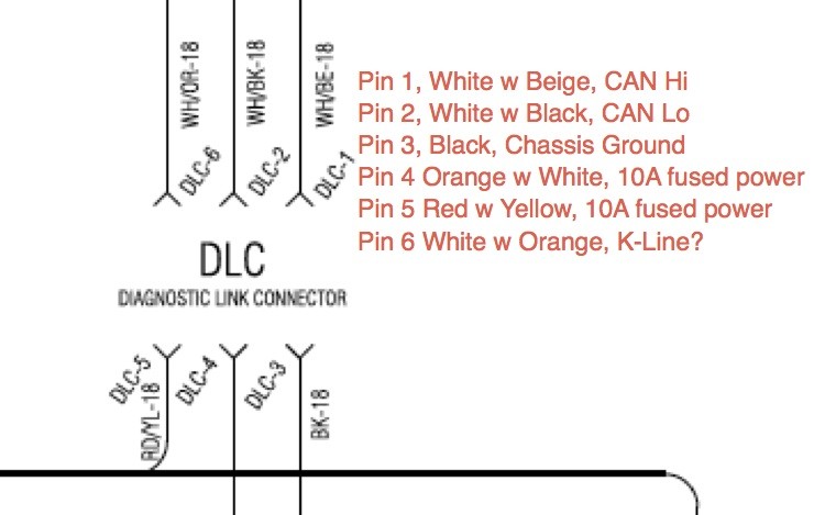
The first step in this endeavor was to delve into the schematics. The Can-Am Spyder features a 6-pin diagnostic connector located under the front hood. According to the wiring diagrams, this connector carries several key signals: a differential CAN (Controller Area Network) pair, a K-line signal, chassis ground, and two +12V accessory power lines, each fused at 10A. It’s important to note that these 10A power lines are not solely dedicated to the diagnostic connector but are shared on a bus with other vehicle components.
My familiarity with CAN bus systems stems from my previous work on the NASA COLBERT treadmill project. This advanced treadmill, used on the International Space Station, utilized CAN bus communication for its motor controller, sourced from Woodway. Further research and insights from helpful members on the spyderlovers forum illuminated the role of the K-line. It appears to serve as an alternative communication physical layer to the CAN bus. Given CAN’s higher bandwidth and multi-drop capabilities, I’m anticipating that the majority of the diagnostic data I’m interested in will be transmitted via the CAN lines.
Acquiring USB to CAN adapters can be a significant expense. The Kvaser interface I utilized during my time at Wyle for the treadmill project was exceptionally capable, but with a price tag around $700, it was too costly for a personal project. Similarly, the Kvaser CAN King software, while excellent, added to the prohibitive cost. Therefore, I opted for a more budget-friendly and versatile solution: the Android Open Accessory Application (AOAA) Kit from Embedded Artists.
The AOAA Kit seemed like a logical choice for several reasons. I already possess a solid working knowledge of the NXP microcontroller family, which forms the heart of the kit, and I’m comfortable with their development tools. My past experiences with Embedded Artists products have consistently been positive, noting their quality construction and comprehensive documentation. To ensure robust and reliable connections, I ordered Deutsch connectors, specifically the DT 6-way series, known for their ruggedness and quality, despite their premium price.
Initially, I held onto a sliver of hope that perhaps some of the CAN traffic might adhere to the OBD-II standard. To test this, once the Deutsch connectors arrived, I fabricated a cable to bridge the Spyder’s diagnostic connector to my OBDPros Bluetooth adapter. This adapter employs an ELM327 compatible chipset, commonly used for extracting OBD-II data. I then used the Torque app on my Android phone to scan the bus, expecting to see some form of OBD-II protocol recognized. Unfortunately, the scan yielded no recognizable OBD-II protocol, confirming my initial suspicions about the proprietary nature of the Spyder’s diagnostics.
Undeterred, I shifted my focus to bringing the AOAA kit online. I encountered a minor learning curve during setup, discovering that the kit demands a full 1A power supply. My initial attempt with an 850mA supply resulted in erratic behavior and flash memory write errors. To streamline the setup, I separated the two microcontrollers on the AOA board and populated the D-sub 9 headers, as RJ-45 connectors without integrated magnetics were unavailable in my lab. A crucial note for anyone working with D-sub 9 interfaces in this context: a female-to-female pass-through connector is required – avoid using a null modem cable. In my case, a standard D-Sub 9 extension cable with a double female adapter resolved the connection.
With the example CAN code successfully compiling, running, and exchanging messages with the demo code, the next task was to create an enclosure for the electronics. Now, I’m a software engineer by trade, and while Sparx Engineering, my company, excels at designing and building sophisticated enclosures for our professional projects, I couldn’t quite tap into those resources for this personal endeavor, at least not yet.
This brings us to the current stage of my Can-Am Spyder diagnostic hacking project, paused temporarily due to unforeseen travel. However, the airplane journey did provide valuable reading time. It appears the demo web server code included with the AOAA kit utilizes the open-source FAT FS library for its document root. My next step is to integrate the CAN communication example with this web server and FAT file system. The goal is to enable logging of the CAN data directly to a disk, and subsequently serve this data over a network for analysis.
To continue following this project, check out Part 2 of this series.