When it comes to diagnosing issues with your 2004 Ford F-150, the OBD2 port is your first point of contact. This port allows mechanics and DIY enthusiasts to pull diagnostic trouble codes, understand what’s going on under the hood, and efficiently troubleshoot problems. However, if your OBD2 scanner isn’t powering up or connecting, a blown fuse might be the culprit. Locating the correct fuse for your 2004 F-150’s OBD2 port is crucial for a quick diagnostic process. This guide will walk you through finding the 2004 F150 Obd2 Fuse Location and understanding the fuse box diagrams of your truck.
Your 2004 Ford F-150, like many vehicles, utilizes fuse boxes to protect its electrical circuits from overloads. For the 2004 F-150 model, you’ll find primarily three fuse box locations. Understanding these locations is the first step in finding the fuse related to your OBD2 port, also known as the diagnostic connector.
Fuse Box Locations on a 2004 Ford F-150
-
Passenger Compartment Fuse Panel: This fuse box is generally the most relevant when looking for interior electrical component fuses, and importantly, the OBD2 fuse location. It’s usually located inside the cabin, often beneath the dashboard on the driver’s side or passenger’s side.
-
Auxiliary Relay Box (with DRL): Some 2004 F-150 models are equipped with Daytime Running Lights (DRL). If your truck has DRL, it might have this auxiliary relay box, typically found in the engine compartment.
-
Auxiliary Relay Box (without DRL): For 2004 F-150s without Daytime Running Lights, there’s another version of the auxiliary relay box, also located in the engine compartment but with a slightly different configuration.
While both auxiliary boxes are important for various vehicle functions, the OBD2 fuse location you’re searching for is almost always situated within the Passenger Compartment Fuse Panel.
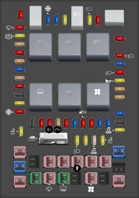
 2004 Ford F-150 Passenger Compartment Fuse Panel Diagram
Finding the OBD2 Fuse in the Passenger Compartment Fuse Box
To pinpoint the 2004 f150 OBD2 fuse location, you’ll need to access the Passenger Compartment Fuse Panel. Refer to your owner’s manual for the exact location, as it can slightly vary. Once you’ve found it, you’ll need to identify the fuse that powers the diagnostic connector.
Based on the fuse box diagram for the 2004 Ford F-150, fuse number 41 in the Passenger Compartment Fuse Panel is designated for the “Diagnostic connector power”. This is a 20 Amp MINI fuse.
It’s always recommended to double-check with your specific vehicle’s owner’s manual for the most accurate fuse assignment, as there can be minor variations depending on the exact trim and options of your 2004 F-150. However, fuse #41 is highly likely to be your 2004 f150 OBD2 fuse location.
Below is a table detailing the fuses in the Passenger Compartment Fuse Panel of a 2004 Ford F-150. This can help you not only locate the OBD2 fuse but also understand the function of other fuses in this primary fuse box.
| Type | No. | Description |
|---|---|---|
| Fuse MINI 10A | 1 | Run/Accessory – Wipers, Instrument cluster |
| Fuse MINI 20A | 2 | Stop/Turn lamps, Speed control deactivate switch |
| Fuse MINI 5A | 3 | Power mirrors, Memory logic power, Memory seats and pedals |
| Fuse MINI 10A | 4 | DVD battery power |
| Fuse MINI 5A | 5 | Keep alive memory for Powertrain Control Module (PCM) and climate control module |
| Fuse MINI 15A | 6 | Parklamps, BSM, Instrument panel illumination |
| Fuse MINI 5A | 7 | Radio (start signal) |
| Fuse MINI 10A | 8 | Heated mirrors, Switch indicator |
| Fuse MINI 20A | 10 | Trailer tow back-up lamps relay (PCB1), Trailer tow parklamp relay (R201) |
| Fuse MINI 10A | 11 | A/C clutch, 4×4 solenoid |
| Fuse MINI 10A | 13 | Climate control module power |
| Fuse MINI 10A | 14 | Back-up lamp and Daytime Running Lamps (DRL) relay coil, A/C pressure switch, Brake-shift interlock solenoid |
| Fuse MINI 5A | 15 | Overdrive cancel, Cluster, Brake-Shift Interlock (BSI) |
| Fuse MINI 10A | 16 | ABS module (Run/Start power) |
| Fuse MINI 15A | 17 | Fog lamp relay (R202) |
| Fuse MINI 10A | 18 | Run/Start feed – Flasher relay, Electrochromatic mirror, Heated seats, BSM, Compass, RSS (Reverse Sensing System) |
| Fuse MINI 10A | 19 | Restraints (Air bag module) |
| Fuse MINI 15A | 20 | PCM 4×4 power |
| Fuse MINI 15A | 21 | Cluster keep alive power |
| Fuse MINI 10A | 22 | Delayed accessory power for audio, power door lock switch and moonroof switch illumination |
| Fuse MINI 10A | 23 | RH low beam headlamp |
| Fuse MINI 15A | 24 | Battery saver power for demand lamps |
| Fuse MINI 10A | 25 | LH low beam headlamp |
| Fuse MINI 20A | 26 | Horn relay (PCB3), Horn power |
| Fuse MINI 5A | 27 | Passenger Air bag Deactivation (PAD) warning lamp, Cluster air bag warning lamp, Cluster RUN /START power |
| Fuse MINI 5A | 28 | SecuriLock transceiver (PATS) |
| Fuse MINI 15A | 29 | PCM 4×4 power |
| Fuse MINI 20A | 31 | Radio power |
| Fuse MINI 15A | 32 | Vapor Management Valve (VMV), A/C clutch relay, Canister vent, Heated Exhaust Gas Oxygen (HEGO) sensors #11 and #21, CMCV, Mass Air Flow (MAF) sensor, VCT |
| Fuse MINI 15A | 33 | Shift solenoid, CMS #12 and #22 |
| Fuse MINI 20A | 34 | Fuel injectors and PCM power |
| Fuse MINI 20A | 35 | Instrument cluster high beam indicator, High beam headlamps |
| Fuse MINI 10A | 36 | Trailer tow right turn/stop lamps |
| Fuse MINI 20A | 37 | Rear power point |
| Fuse MINI 25A | 38 | Subwoofer power |
| Fuse MINI 20A | 39 | Instrument panel power point |
| Fuse MINI 20A | 40 | Low beam headlamps, DRL |
| Fuse MINI 20A | 41 | Cigar lighter, Diagnostic connector power |
| Fuse MINI 10A | 42 | Trailer tow left turn/stop lamps |
| Fuse FMX/JCase 30A | 101 | Starter solenoid |
| Fuse FMX/JCase 20A | 102 | Ignition switch feed |
| Fuse FMX/JCase 20A | 103 | ABS valves |
| Fuse FMX/JCase 30A | 105 | Electric trailer brakes |
| Fuse FMX/JCase 30A | 106 | Trailer tow battery charge |
| Fuse FMX/JCase 30A | 107 | Power door locks (BSM) |
| Fuse FMX/JCase 30A | 108 | Passenger power seat |
| Fuse FMX/JCase 30A | 109 | Driver power seat, Adjustable pedals |
| Fuse FMX/JCase 30A | 111 | 4×4 relays |
| Fuse FMX/JCase 40A | 112 | ABS pump power |
| Fuse FMX/JCase 30A | 113 | Wipers and washer pump |
| Fuse FMX/JCase 40A | 114 | Heated backlite, Heated mirror power |
| Fuse FMX/JCase 30A | 116 | Blower motor |
| Fuse FMX/JCase 30A | 118 | Heated seats |
| Circuit breaker MAXI 40A | 401 | Power windows, Moonroof, Power sliding backlite |
| Relay | R01 | Starter solenoid |
| Relay | R02 | Accessory delay |
| Relay | R03 | Hi-beam headlamps |
| Relay | R04 | Heated backlite |
| Relay | R05 | Trailer tow battery charge |
| Relay | R06 | Blower motor |
| Relay | R201 | Trailer tow park lamps |
| Relay | R202 | Fog lamps |
| Relay | R203 | PCM |
Why is the OBD2 Fuse Important?
The OBD2 port is essential for modern vehicle diagnostics. It’s the gateway for communicating with your 2004 F-150’s computer systems. Mechanics and technicians use scanners that plug into this port to read trouble codes, access live data, and perform various diagnostic tests.
If the OBD2 fuse is blown, the port will not receive power, and your scanner won’t be able to connect or power on when plugged in. This can halt any diagnostic efforts, making it seem like there’s a bigger problem than a simple blown fuse.
Troubleshooting and Replacing the OBD2 Fuse
If you suspect a blown OBD2 fuse, here’s what you should do:
- Locate the Passenger Compartment Fuse Box: Refer to your owner’s manual for the exact location.
- Identify Fuse #41: Using the diagram (often found on the fuse box cover or in your manual) and the table above, locate fuse number 41, the 20 Amp MINI fuse.
- Inspect the Fuse: Carefully pull out the fuse. You can use a fuse puller tool (often included in the fuse box) or needle-nose pliers. Hold the fuse up to the light and check the thin wire inside. If the wire is broken or melted, the fuse is blown.
- Replace the Fuse: Use a new 20 Amp MINI fuse to replace the blown one. Important: Always replace a blown fuse with one of the same amperage rating. Using a higher amperage fuse can damage the circuit.
- Test Your OBD2 Port: After replacing the fuse, try plugging in your OBD2 scanner again to see if it powers up and connects to your vehicle’s computer.
Safety Tip: Before working with fuses, turn off your vehicle’s ignition and ensure the engine is off.
Finding the 2004 f150 OBD2 fuse location and checking its condition is a simple yet crucial step in diagnosing any electrical or engine-related issues. By understanding your fuse box diagrams and knowing the function of each fuse, you can save time and potentially money on diagnostics and repairs for your Ford F-150. Always consult your owner’s manual for the most accurate and vehicle-specific information regarding fuse locations and ratings.