The BMW 5 Series E39, produced from 1996 to 2003, remains a popular choice for car enthusiasts and everyday drivers alike. Known for its blend of performance and luxury, the 1998 BMW 5 Series, in particular, is a sought-after model year within the E39 generation. Maintaining this classic vehicle requires understanding its systems, and a crucial aspect is knowing the location of its fuses, especially those related to the OBD2 (On-Board Diagnostics II) system. If you’re troubleshooting electrical issues or simply performing routine maintenance on your 1998 BMW 5 Series, understanding the fuse box locations and layouts is essential.
This guide provides a detailed overview of the fuse box locations in your 1998 BMW 5 Series (E39), covering various models including 520i, 520d, 523i, 525d, 525td, 525tds, 528i, 530i, 530d, 535i, and 540i. We will explore each fuse panel, providing diagrams and assignments to help you quickly locate the correct fuse for your needs. While this article focuses on the 1998 model year, the fuse box locations and layouts are generally consistent across the E39 generation from 1996 to 2003.
For information on other BMW 5-Series models, you can also explore:
BMW 5-Series (E60/E61; 2003-2010)
BMW 5-Series (F10/F11/F07/F18; 2011-2017)
Fuse Box Locations in Your 1998 BMW 5 Series (E39)
The 1998 BMW 5 Series E39 has multiple fuse boxes located in different areas of the vehicle. These locations are strategically chosen to protect various electrical circuits and systems. Understanding where to find each fuse box is the first step in diagnosing and resolving electrical problems. The primary fuse box locations are:
- Engine Compartment Fuse Box: Located under the hood.
- Glove Compartment Fuse Box: Inside the glove compartment.
- Footwell Fuse Block: Positioned in the passenger footwell.
- Luggage Compartment Fuse Boxes: In the trunk area.
Let’s examine each location in detail.
1. Engine Compartment Fuse Box
The engine compartment fuse box houses fuses and relays crucial for engine management and related systems. This is often the first place to check for issues related to engine performance, starting problems, or sensor malfunctions.
Fuse Box Location
The engine compartment fuse box in your 1998 BMW 5 Series is typically situated on the passenger side of the engine bay, near the windshield. It is enclosed in a black plastic box with a cover that needs to be opened to access the fuses.
Diagram and Fuse Assignments (Type 1)
Depending on the specific production date and model variant of your 1998 BMW 5 Series, there might be slight variations in the fuse box layout. Here is a diagram for one type of engine compartment fuse box commonly found in the E39. Always refer to the diagram located on the inside of your fuse box cover for the most accurate layout for your vehicle.
| № | Component |
|---|---|
| 1 | Engine control module |
| 2 | Transmission control module |
| 3 | Engine control module fuse |
| 4 | Engine control module relay |
| 5 | Windscreen wiper motor relay I |
| 6 | Windscreen wiper motor relay II |
| 7 | Air conditioning condenser blower motor relay I |
| 8 | Air conditioning condenser blower motor relay III |
| 9 | ABS relay |
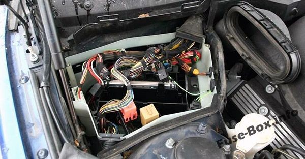
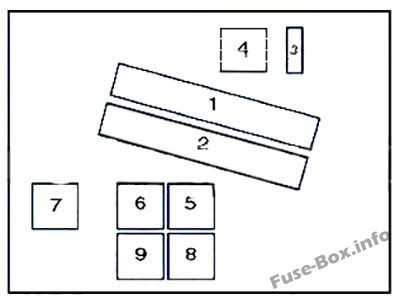
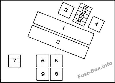
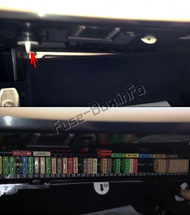
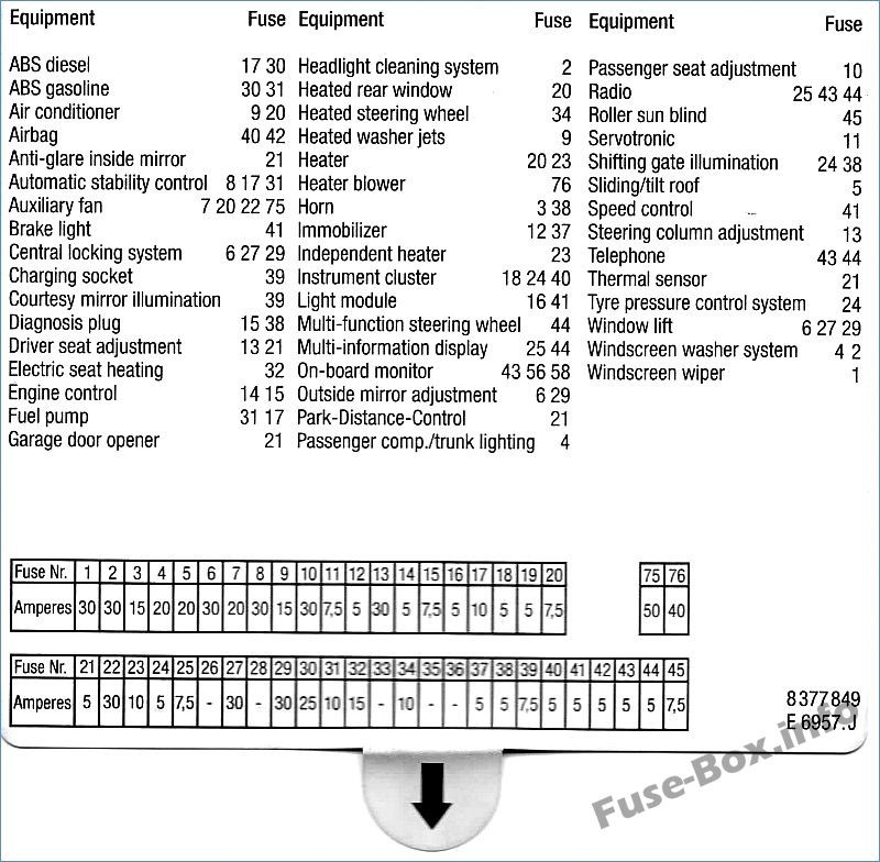
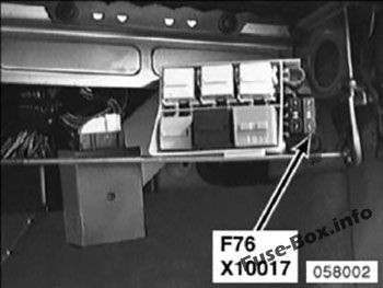

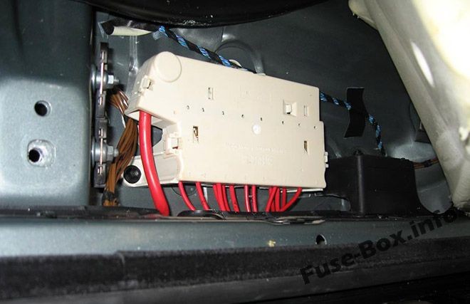
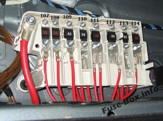
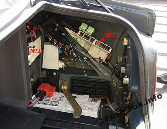
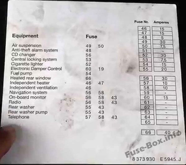
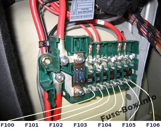
Diagram and Fuse Assignments (Type 2)
Here is another type of engine compartment fuse box diagram that may be present in your 1998 BMW 5 Series E39. Again, prioritize the diagram on your fuse box cover if available.
| № | A | Component |
|---|---|---|
| 1 | Engine control module (ECM) | |
| 2 | Transmission control module (TCM) | |
| 3 | Engine control (EC) relay | |
| 4 | Ignition coil relay – except 520i (22 6S 1)/525i/530i | |
| 5 | Windscreen wiper motor relay 1 | |
| 6 | Windscreen wiper motor relay 2 | |
| 7 | AC condenser blower motor relay 1 (until 03/98) | |
| 8 | AC condenser blower motor relay 3 (until 03/98) | |
| 9 | Secondary air injection (AIR) pump relay | |
| F1 | 30A | Engine control module (ECM), evaporative emission (EVAP) canister purge valve, mass airflow (MAF) sensor, camshaft position (CMP) sensor 1, engine coolant thermostat – 535i/540i |
| F2 | 30A | Secondary air injection (AIR) pump, intake manifold air control solenoid, injectors (except 520i (22 6S1)/525i/530i), engine control module (ECM), evaporative emission (EVAP) canister purge valve, camshaft position (CMP) actuator 1 & 2, idle speed control (ISC) actuator |
| F3 | 20A | Crankshaft position (CKP) sensor, camshaft position (CMP) sensor 1 & 2, mass airflow (MAF) sensor |
| F4 | 30A | Heated oxygen sensors (H02S), transmission control module (TCM) |
| F5 | 30A | Ignition coil relay – except 520i (22 6S1)/525i/530i |
2. Glove Compartment Fuse Box
The glove compartment fuse box is a primary location for fuses controlling interior electronics, comfort features, and potentially systems related to the OBD2 port and diagnostic functions.
Fuse Box Location
To access the glove compartment fuse box, open the glove compartment. You will see two plastic clamps at the top of the glove box opening. Turn these clamps to the left and pull the panel down. The fuse box will be located behind this panel.
Diagram and Fuse Assignments (Until 03.1998)
Fuse layouts in the glove compartment can vary, and it’s crucial to check the diagram located inside your fuse box cover. Here’s a diagram for models produced until March 1998:
| № | A | Component |
|---|---|---|
| F1 | 30A | Windscreen wiper motor relay |
| F2 | 30A | Headlamp washers |
| F3 | 15A | Horn |
| F4 | 20A | Multifunction control module |
| F5 | 20A/30A | Sunroof |
| F6 | 30A | Electric door mirror, passenger’s side |
| F7 | 20A/30A | AC condenser blower motor relay 1 |
| F8 | – | – |
| F9 | 15A | AC/ heater control module |
| F10 | 30A | Seat adjustment-passenger’s side |
| F11 | 7,5A | Multifunction control module- variable power steering |
| F12 | 5A | Immobilizer |
| F13 | 30A | Seat adjustment-driver’s side, steering column adjustment |
| F14 | 5A | Engine control module (ECM) |
| F15 | 7,5A | Transmission control module (TCM), engine oil level sensor, alternator, electrics box temperature switch (530d) |
| F16 | 5A | Lamps control module |
| F17 | 10A | Fuel pump relay, ABS control module, multi switch assembly |
| F18 | 5A | Instrument panel |
| F19 | 5A | Overvoltage protection relay 2 |
| F20 | 5A/7.5A | AC/heater control module, heated rear window relay, tyre pressure monitor control module |
| F21 | 5A | Cigarette lighter relay, seat adjustment relay/steering column adjustment relay, garage door opener, parking aid control module, anti-dazzle interior mirror |
| F22 | 30A | AC condenser blower motor relay 2 |
| F23 | 7,5A | Digital multifunction display-rear |
| F24 | 5A | Instrument panel, tyre pressure monitor control module, steering position sensor |
| F25 | 7,5A | Digital multifunction display |
| F26 | – | – |
| F27 | 30A | Multifunction control module |
| F28 | 15A | Automatic transmission (AT) |
| F29 | 30A | Door function control module, driver’s side |
| F30 | 25A | ABS control module |
| F31 | 10A | Fuel pump relay, ABS control module, secondary air injection (AIR) pump relay (petrol) |
| F32 | 25A | Multi switch assembly |
| F33 | – | – |
| F34 | 10A | Multifunction steering wheel/airbag assembly, heated steering wheel |
| F35 | 5A | AC condenser blower motor, rear |
| F36 | – | – |
| F37 | 5A | Immobilizer control module |
| F38 | 5A | Multifunction control module, horn relay, rain sensor, transmission shift hold switch (AT), data link connector (DLC) |
| F39 | 7,5A | Vanity mirror lamps, rechargeable torch |
| F40 | 5A | Instrument panel, seat adjustment control module, airbag crash sensor, seat belt contact switch (drivers side) |
| F41 | 5A | Lamps control module, clutch pedal position (CPP) switch, brake pedal position (BPP) switch |
| F42 | 5A | SRS control module |
| F43 | 5A | Over voltage protection relay 1 |
| F44 | 5A | Multifunction steering wheel/airbag assembly, steering wheel, digital multifunction display-front/rear |
| F45 | 7,5A | Multi switch assembly |
OBD2 Fuse Location in 1998 BMW 5 Series:
While there isn’t a fuse explicitly labeled “OBD2 fuse,” fuse F38 (5A) in the glove compartment fuse box (for models until 03.1998) is associated with the data link connector (DLC), which is the OBD2 port. If you are experiencing issues with your OBD2 scanner not powering on or connecting to your 1998 BMW 5 Series, checking fuse F38 is a crucial first step. A blown F38 fuse can prevent power from reaching the OBD2 port, thus hindering diagnostic communication.
Diagram and Fuse Assignments (Since 03.1998)
For 1998 BMW 5 Series E39 models manufactured from March 1998 onwards, the glove compartment fuse box layout might slightly differ. Here’s the diagram for later models:
| № | A | Component |
|---|---|---|
| F1 | 30A | Windscreen wiper motor relay |
| F2 | 30A | Headlamp washers |
| F3 | 15A | Horn |
| F4 | 20A | Multifunction control module |
| F5 | 20A/30A | Sunroof |
| F6 | 30A | Electric door mirror, passenger’s side |
| F7 | 20A/30A | Cigarette lighter-front (09/00) |
| F8 | – | – |
| F9 | 15A | AC/heater control module |
| F10 | 30A | Seat adjustment-passenger’s side |
| F11 | 7,5A | Multifunction control module- variable power steering |
| F12 | 5A | Immobilizer |
| F13 | 30A | Seat adjustment-driver’s side, steering column adjustment |
| F14 | 5A | Engine control module (ECM) |
| F15 | 7,5A | Transmission control module (TCM), engine oil level sensor, alternator, electrics box temperature switch (530d) |
| F16 | 5A | Lamps control module |
| F17 | 10A | Fuel pump relay, ABS control module, multi switch assembly |
| F18 | 5A | Instrument panel |
| F19 | 5A | Overvoltage protection relay 2 |
| F20 | 5A/7.5A | AC/heater control module, heated rear window relay, tyre pressure monitor control module |
| F21 | 5A | Cigarette lighter relay, seat adjustment relay/steering column adjustment relay, garage door opener, parking aid control module, anti-dazzle interior mirror |
| F22 | 25A | Fuel pumprelay-530d/520i(226S1)/525i/530i |
| F23 | 7,5A | Digital multifunction display-rear |
| F24 | 5A | Instrument panel, tyre pressure monitor control module, steering position sensor |
| F25 | 7,5A | Digital multifunction display |
| F26 | – | – |
| F27 | 30A | Multifunction control module |
| F28 | 15A | Automatic transmission (AT) |
| F29 | 30A | Door function control module, driver’s side |
| F30 | 25A | ABS control module |
| F31 | 10A | Fuel pump relay, ABS control module, secondary air injection (AIR) pump relay (petrol) |
| F32 | 25A | Multi switch assembly |
| F33 | – | – |
| F34 | 10A | Multifunction steering wheel/air bag assembly, heated steering wheel |
| F35 | 5A | AC condenser blower motor, rear |
| F36 | – | – |
| F37 | 5A | Immobilizer control module |
| F38 | 5A | Multifunction control module, horn relay, rain sensor, transmission shift hold switch (AT), data link connector (DLC) |
| F39 | 7,5A | Vanity mirror lamps, rechargeable torch |
| F40 | 5A | Instrument panel, seat adjustment control module, airbag crash sensor, seat belt contact switch (driver’s side) |
| F41 | 5A | Lamps control module, clutch pedal position (CPP) switch, brake pedal position (BPP) switch |
| F42 | 5A | SRS control module |
| F43 | 5A | Overvoltage protection relay 1 |
| F44 | 5A | Multifunction steering wheel/air bag assembly, steering wheel, digital multifunction display-front/rear |
| F45 | 7,5A | Multi switch assembly |
Notably, even in the later layout, F38 (5A) remains associated with the data link connector (DLC), reinforcing its importance for OBD2 port functionality in your 1998 BMW 5 Series.
Relay Block in the Glove Compartment
Behind the fuse box in the glove compartment, you’ll find a relay block. Relays are switches that control higher-current circuits.
Location
The relay block is directly behind the glove compartment fuse box, accessible once the fuse box panel is lowered.
Diagram and Relay Assignments
| № | component |
|---|---|
| 1 | AC condenser blower motor relay 2 (until 03/98) |
| 2 | Headlamp washer pump relay |
| 3 | – |
| 4 | Starter motor relay |
| 5 | Seat adjustment relay/steering column adjustment relay |
| 6 | Heater blower relay |
| F75 | (50A) AC condenser blower motor/engine coolant blower motor |
| F76 | (40A) AC/heater blower control module |
3. Block in the Footwell
Another fuse and relay location is in the passenger footwell. This block often contains high-amperage fuses that protect major electrical systems.
Location
The footwell block is located on the right side of the car, under the floor lining in the passenger footwell. You may need to remove some trim panels to access it.
Diagram and Fuse Assignments
| № | A | Component |
|---|---|---|
| F107 | 50A | Secondary air injection (AIR) pump relay |
| F108 | 50A | ABS control module |
| F109 | 80A | Engine control (EC) relay, fuse box-engine bay (F4&F5) |
| F110 | 80A | Fuse box-fascia 1 (F1-F12&F22-F25) |
| F111 | 50A | Ignition switch |
| F112 | 80A | Lamps control module |
| F113 | 80A | Seat adjustment relay/steering column adjustment relay, fuse box-fascia 1 (F27-F30), fuse box-fascia 2 (F76), lamps control module, fuse box-fascia 1 (F13)-with lumbar support |
| F114 | 50A | Ignition switch, data link connector (DLC) |
Interestingly, fuse F114 (50A) in the footwell block is also listed as being associated with the data link connector (DLC). This suggests there might be redundancy or a different circuit path depending on the specific system powered. If you are still facing OBD2 port issues after checking glove compartment fuse F38, inspecting footwell fuse F114 would be the next step.
4. Fuse Boxes in the Luggage Compartment (Trunk)
The luggage compartment, or trunk, houses fuse boxes that control rear vehicle systems, audio components, and other accessories.
Fuse Box Location
The luggage compartment fuse boxes are located on the right side of the trunk, behind a trim cover.
Box 1 Diagram and Fuse Assignments (Type 1)
Like other fuse boxes, luggage compartment layouts can vary. Here’s a diagram for one type of fuse box 1 in the trunk:
| № | A | Component |
|---|---|---|
| 1 | Overvoltage protection relay 1 | |
| 2 | Fuel pump relay | |
| 3 | Heated rear window relay | |
| 4 | Overvoltage protection relay 2 | |
| 5 | Fuel filler flap relay | |
| F46 | – | – |
| F47 | 15A/20A | Auxiliary heater |
| F48 | 5A | Anti-dazzle interior mirror, alarm system in car movement control module, alarm system gradient sensor, alarm system horn |
| F49 | 30A | Suspension compressor relay |
| F50 | 7,5A | Suspension control module (with air suspension) |
| F51 | 30A | Cigarette lighter- rear |
| F52 | 30A | Cigarette lighter relay, cigarette lighter-front |
| F53 | 5A | Aerial signal amplifier, boot lid/tail gate lockstitch |
| F54 | 15A | Fuel pump relay |
| F55 | 20A | Rear screen wash/wipe relay |
| F56 | 30A | Audio unit, navigation system control module, audio unit output amplifier, audio unit CD changer, in-car monitor |
| F57 | 10A | Telephone |
| F58 | 10A | Overvoltage protection relay 1 |
| F59 | 20A | Trailer socket |
| F60 | 15A | Suspension control module, multi switch assembly |
| F61 | 25A | Rear seat heater switch, left, rear seat heater switch, right |
| F62 | – | – |
| F63 | – | – |
| F64 | – | – |
| F65 | – | – |
| F66 | 40A | Heated rear window relay |
| F67 | – | – |
Box 1 Diagram and Fuse Assignments (Type 2)
Here’s the second type of fuse box 1 layout you might find in the trunk of your 1998 BMW 5 Series:
| № | A | Component |
|---|---|---|
| 1 | Ignition main circuits relay | |
| 2 | Fuel pump relay | |
| 3 | Heated rear window relay | |
| 4 | Ignition auxiliary circuits relay | |
| 5 | Independent heater relay | |
| F46 | 15A | independent heater/ventilation |
| F47 | 15A | independent heater |
| F48 | 5A | Alarm system |
| F49 | 30A | Air suspension system |
| F50 | 7,5A | Air suspension system |
| F51 | – | – |
| F52 | 30A | Cigarette lighter |
| F53 | 7,5A | Central locking system |
| F54 | 15A | Fuel pump |
| F55 | – | – |
| F56 | 30A | Audio system, navigation system, on-board monitor |
| F57 | 10A | Cellular phone |
| F58 | 10A | Audio unit, on-board monitor, navigation system, telephone |
| F59 | – | – |
| F60 | 15A | Suspension adjustment control |
| F61 | – | – |
| F62 | – | – |
| F63 | – | – |
| F64 | – | – |
| F65 | – | – |
| F66 | 40A | Heated rear window |
| F67 | – | – |
| F6S | – | – |
| F69 | – | – |
| F70 | – | – |
| F71 | – | – |
| F72 | – | – |
| F73 | – | – |
| F74 | – | – |
Box 2 Diagram and Fuse Assignments
The second fuse box in the luggage compartment (box 2) often houses high-current fuses that feed power to other fuse boxes in the vehicle.
| № | A | Component |
|---|---|---|
| F100 | 200A | Fuse box-footwall (F107-F114) |
| F101 | 80A | Fuse box – load area 1 (F46-F50, F66) |
| F102 | 80A | Fuse box-load area 1 (F51-F55) |
| F103 | 50A | Trailer control module |
| F104 | 50A | Overvoltage protection relay 2 |
| F105 | 100A | Fuse box-fascia 2 (F75), auxiliary heater |
| F106 | 80A | Fuse box-load area 1 (F56-F59) |
Conclusion
Understanding the fuse box locations and fuse assignments in your 1998 BMW 5 Series (E39) is crucial for effective vehicle maintenance and troubleshooting. Specifically, for OBD2 port issues, checking fuse F38 in the glove compartment and potentially F114 in the footwell block should be your initial steps. Always consult the fuse diagrams located on the inside of your fuse box covers for the most accurate information for your specific vehicle, as variations can occur. By using this guide, you can confidently navigate the fuse system of your classic BMW E39 and keep it running smoothly for years to come.
For further information, explore these helpful resources:
How to check the fuses?
How to replace a blown fuse?
Why do car fuses blow?
Types of automotive fuses