Upgrading your vehicle with a Banks Power iDash is a smart move for monitoring performance and diagnostics. A crucial component in this setup is the Bank Power Obd2 Interface Cable. This cable acts as the vital link, allowing your iDash to communicate with your vehicle’s computer system. This guide provides a detailed walkthrough on mounting and connecting your iDash using the OBD2 interface cable, ensuring a seamless installation and optimal performance.
Step-by-Step OBDII Connection for Standard Vehicles
For most vehicles with a standard OBDII communication system, connecting your Banks Power iDash is straightforward. Follow these steps to establish a reliable connection:
-
Locate Your Vehicle’s OBDII Port:
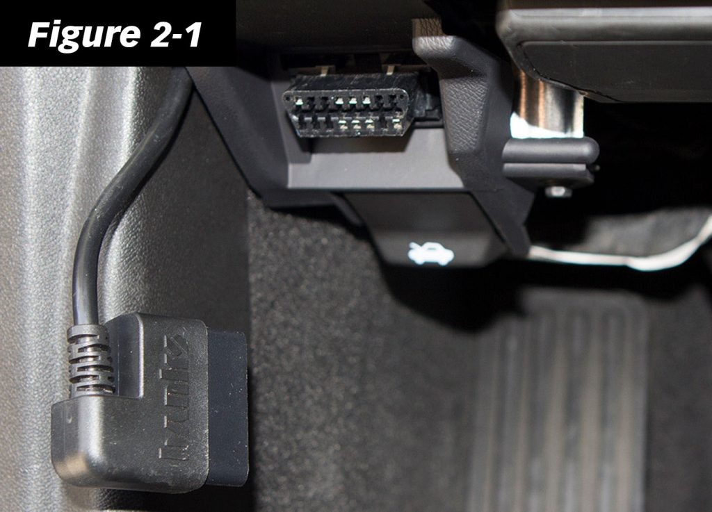
The OBDII port is your vehicle’s diagnostic gateway, typically located beneath the dashboard on the driver’s side. It’s often found near the steering column, but if you are unsure, consult your vehicle’s owner’s manual for the precise location.
-
Connect the Banks OBDII Cable:
Carefully plug the Banks OBDII cable into the vehicle’s OBDII port. Ensure it’s firmly seated for a stable connection.
Important Note: In some vehicle models, the factory OBDII port might be mounted in a way that puts stress on the Banks OBDII cable. If this is the case, you may need to unclip or unscrew the OBDII port from its mounting location temporarily. Relocate the port to a position that allows the Banks cable to connect without bending or strain. Secure the OBDII port under the dash after connecting the cable.
-
Route the OBDII Cable to the iDash Location:
Plan the cable routing from the OBDII port to where you intend to mount your iDash. You may need to carefully tuck the cable behind dash panels or crevices to achieve a clean and concealed installation. Loosening or temporarily removing dash panels can provide easier access for routing the interface cable.
-
Connect the OBDII Cable to the iDash:
Locate the 4-pin port on your iDash. Connect the Banks OBDII cable connector to this port, ensuring the locking tab is facing upwards.
Refer to Figure 2-3 in your iDash manual if you have the standard iDash, or Figure 2-4 for the iDash Banks Bus 1 model for visual confirmation.
Note: If you are installing multiple iDash gauges, consult section 2.7 Advanced B-Bus Network – Multiple iDash for proper connection procedures.
Connecting to Banks Bus 1 Tuners: Six-Gun, EconoMind, SpeedBrake
For users integrating their iDash with Banks Bus 1 products like Six-Gun, EconoMind, or SpeedBrake tuners, the OBDII cable is slightly different. These cables include an extra wire that facilitates communication with these specific Banks tuners.
This additional wire needs to be connected to your Banks Bus 1 tuner to enable seamless data exchange and control between the iDash and the tuner. Refer to the specific installation manual for your Banks Bus 1 tuner for detailed instructions on this additional connection.
Ford 6.0L Power Stroke Specific OBDII Cable Installation
For Ford 6.0L Power Stroke applications, an additional step is required when installing the OBDII cable. A connection to the fuse box is necessary using a provided fuse tap to ensure proper power supply and communication.
-
Access the Fuse Panel and Locate Fuse #22:
Remove the panel beneath the steering wheel to access the fuse panel. Locate Fuse #22 as indicated on the fuse panel diagram (consult your vehicle’s owner’s manual if needed). Carefully remove Fuse #22.
-
Install the Fuse Tap:
Apply the provided fuse tap to Fuse #22. This tap allows you to reinstate the original fuse function while providing a connection point for the OBDII cable. Reinstall the fuse with the fuse tap into the Fuse #22 slot.
-
Connect the Red Terminal Connector:
Route the female red terminal connector from the Ford 6.0L OBDII cable to the fuse tap installed in the previous step. Ensure a secure connection. After this connection, proceed with the standard OBDII cable routing and iDash connection as described in Step 1 of the standard vehicle installation.
For detailed operation instructions regarding Six-Gun, EconoMind, and Speed Brake modules in conjunction with your iDash, please refer to Section 11 of the iDash manual.
Connecting without OBDII or Aftermarket ECU
In scenarios where an OBDII connection is not feasible, or when using an aftermarket ECU, you will need to consult the iDash Aftermarket ECU Setup Owner’s Manual 97670. This manual provides detailed wiring instructions for connecting your iDash directly to an aftermarket ECU or in non-OBDII compliant vehicles.
General iDash Mounting Guidelines
While this article focuses on the OBDII cable connection, understanding general iDash mounting is also helpful for a complete installation. Here are basic guidelines for mounting your iDash:
-
Prepare the Mounting Surface:
Position the mounting sleeve behind your intended mounting surface. Route all necessary cables (OBDII, Aftermarket ECU harness, Starter Cable) through the mounting hole to the iDash location.
-
Connect Cables to iDash Ports:
Connect all routed cables to their respective ports on the iDash (4-Pin and 6-Pin Ports).
-
Insert iDash Studs:
Insert the studs on the back of the iDash through the holes in the mounting sleeve and your mounting surface.
-
Secure with Thumb Nuts:
Hand-tighten the provided nylon thumb nuts onto the iDash studs from behind the mounting surface to secure the iDash in place.
Important Note: Avoid over-tightening the mount. Excessive tightness can cause the iDash buttons to become unresponsive. If you encounter button unresponsiveness, slightly loosen the thumb nuts. If using an aftermarket mount hole (and not the mounting sleeve), ensure the hole provides minimal press fit. Sanding the hole (not the mounting sleeve) might be necessary to achieve proper clearance for button functionality.
Understanding B-Bus Networks: Single and Multiple iDash Setups
The Banks Bus (B-Bus) network allows for expansion and integration of multiple iDash gauges and modules. Understanding simple and advanced B-Bus network configurations is crucial for maximizing your iDash system’s capabilities.
Simple B-Bus Network – Single iDash Configuration
A basic B-Bus network for a single iDash gauge can include an In-Cab Terminator OR a Jumper Block Termination, a B-Bus Starter Cable, a B-Bus Module, and a Black Termination Cap, as illustrated below.
For iDash Hardware Rev 1:
A. Connect the Starter Cable to the In-Cab Terminator. (Step A in diagram)
B. Connect the In-Cab Terminator to the iDash 6-Pin Port. (Step B in diagram)
For iDash Hardware Rev 2:
A. Connect the Starter Cable directly to the iDash 6-Pin Port (without the In-Cab Terminator).
B. Ensure the Jumper Block is connected to the iDash 2-Pin termination (See Figure 2-12 in the original document for visual reference).
Advanced B-Bus Network – Multiple iDash Configuration
You can expand your B-Bus network to include up to three additional iDash units. Each additional iDash requires a Y-Cable for connection.
The primary iDash in a multi-gauge setup is the one connected to the OBDII cable or aftermarket ECU harness. Only the primary iDash will support advanced features like:
- Vehicle Diagnostics (Reading/Clearing Diagnostic Trouble Codes and Emissions Readiness)
- Wake-up sensitivity settings
- Data logging
- Speed correction settings
Setting up an Advanced B-Bus Network:
-
For HW Rev 1 iDash Units Only:
A. Connect the In-Cab Terminator to the primary iDash’s 6-pin port. Only one In-Cab Terminator is needed in the entire network. (Step A in Figure 2-11)
B. Connect a Y-Cable to the In-Cab Terminator and then to the second iDash. (Step B in Figure 2-11)
C. For each additional iDash, use another Y-Cable in series.
D. Connect the Starter Cable to the Y-Cable at the end of the chain. (Step C in Figure 2-11) -
For HW Rev 2 iDash Units Only:
A. Connect a Y-Cable to the 6-pin port of the first (primary) iDash and then to the second iDash (without using the In-Cab Terminator). (Step B in Figure 2-11)
B. Connect the Starter Cable to the Y-Cable at the end of the chain. (Step C in Figure 2-11)
C. Remove any extra Jumper Blocks from the 2-Pin terminations of the added iDash units. Only one Jumper Block terminator is required in the entire network. (See Figure 2-12 in the original document for visual reference). -
Mixing HW Rev 1 and Rev 2 iDash Units:
If your network includes both HW Rev 1 and Rev 2 iDash units, follow either the Rev 1 or Rev 2 instructions, but ensure you only use a single terminator (either In-Cab Terminator or Jumper Block) within the entire B-Bus network.
Verifying B-Bus Network Termination Type
Proper termination is critical for a stable and reliable B-Bus network, especially when using multiple iDash gauges or Banks modules. Only one termination should be present within the network to prevent communication issues.
Identify Your iDash Hardware Revision:
Physically inspect the back of your iDash (as shown in Figure 2-12 & Figure 2-13 of the original document) to visually confirm the presence of a Jumper Block Termination. Alternatively, you can check the “Hardware Rev:” in the “System Information” menu of your iDash display (as shown in Figure 2-14 of the original document).
Termination Guidelines Based on Hardware Revision:
- Hardware Revision 1: Must use the In-Cab Terminator in the B-Bus network.
- Hardware Revision 2: Will have a pre-installed Jumper Block Termination. Do NOT use the In-Cab Terminator with HW Rev 2 iDash units.
By carefully following these instructions, you can confidently connect your Banks Power iDash using the OBD2 interface cable and establish a robust and reliable monitoring system for your vehicle. Remember to always consult the official Banks Power documentation for the most accurate and up-to-date information for your specific iDash model and vehicle application.