Unlocking your car’s diagnostic data can be incredibly insightful for enthusiasts and DIYers alike. By connecting an Arduino to your car’s On-Board Diagnostics II (OBD2) port using a modified ELM327 adapter, you can access a wealth of real-time information about your vehicle’s performance. This guide will walk you through the process of modifying an inexpensive ELM327 OBD2 adapter for seamless serial communication with your Arduino, allowing you to create custom car monitoring and data logging projects.
To begin, you’ll need to carefully disassemble your ELM327 OBD2 adapter. Most of these adapters come in a plastic enclosure that is typically held together by screws.
First, peel off any stickers covering the enclosure of your ELM327 cable. Once the sticker is removed, you’ll likely find four small screws, often requiring a star screwdriver to unscrew them. Carefully remove these screws and set them aside.
Alt text: Disassembled ELM327 OBD2 adapter showing the internal circuit board after removing the screws from the enclosure, preparing for modification.
With the screws removed, gently separate the two halves of the enclosure to reveal the circuit board inside.
Tip: Before completely removing the circuit board, especially if your adapter has a connector linking the board to the OBD2 plug, it’s a good idea to mark one side of the connector with nail polish or a marker. This will help you correctly re-orient the connector during reassembly, although for this modification, complete removal of this connector isn’t strictly necessary.
Next, the crucial step is to prepare the board for serial communication with your Arduino. This involves soldering wires to the Transmit (TX) and Receive (RX) pins on the ELM327 chip. Refer to the datasheet of your specific USB bridge chip or the common pin-out configurations for ELM327 boards to accurately identify the TX and RX pins. The following image highlights typical locations for these pins.
Alt text: Close-up of an ELM327 circuit board highlighting the typical locations of the TX (Transmit) and RX (Receive) pins required for soldering wires for Arduino serial communication.
Carefully solder two wires to the identified TX and RX pins on the board. Exercise caution during soldering to avoid accidentally desoldering nearby small surface mount components. Using a soldering iron with a fine tip and working in a well-lit area is recommended.
Tip: To verify you’re connecting to the correct points for serial communication, you can use a simple Arduino test. Program your Arduino to send serial data with short delays. Connect a jumper wire to the Arduino’s TX pin and gently probe around the ELM327 board with the other end of the jumper while monitoring serial activity. Surface-mounted LEDs on the board might flicker when you touch a point that is transmitting or receiving serial data, indicating a potential connection point. While this method is less reliable for identifying the RX pin, the provided images should clearly indicate the correct soldering locations for both TX and RX.
Alt text: ELM327 circuit board with wires soldered to the TX and RX pins, prepared for connecting to an Arduino for OBD2 serial data exchange.
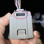
A critical modification to ensure proper communication with your Arduino and prevent conflicts with a computer is to isolate the USB communication of the ELM327 adapter. The standard USB connection is designed for direct PC communication, which we want to bypass in favor of Arduino control. This is achieved by modifying the USB connector that connects the USB cable to the ELM327 board. Typically, this connector has four pins. To disable PC communication while still providing power from the USB port, carefully cut or remove the middle two pins (data pins D+ and D-). This modification ensures that the ELM327 adapter only draws power from the USB port and the serial controller remains free for Arduino communication.
Alt text: Modified USB connector on the ELM327 board with the middle two data pins removed to disable PC communication and dedicate serial lines to Arduino.
Once the soldering and USB modification are complete, carefully place the modified circuit board back into the enclosure. If the original screw enclosure is cumbersome for your intended use, especially in tight spaces like under the dashboard, you can temporarily tape the enclosure shut for testing and prototyping. For permanent installations, consider a more robust enclosure solution.
With these modifications, your ELM327 adapter is now ready to interface with your Arduino via serial communication. You can now connect the soldered wires to the appropriate RX and TX pins on your Arduino board and start developing your OBD2 data acquisition and processing projects. Remember to consult the ELM327 command set documentation to send commands and interpret the data received from your car’s OBD2 system.