Connecting your Arduino to your car’s On-Board Diagnostics II (OBD2) system opens up a world of possibilities for vehicle monitoring and data analysis. The key to bridging this gap is the Arduino Obd2 Connector, often used in conjunction with an ELM327 interface. This combination allows enthusiasts and professionals alike to tap into the wealth of information provided by your car’s Engine Control Unit (ECU).
The foundation of this connectivity lies in the ELM327 chip. Originally developed by Elm Electronics, the ELM327 is a microcontroller firmware designed to decode various vehicle communication protocols into a standardized ASCII format. This ingenious device acts as a translator, making it possible to communicate with different car makes and models, despite their diverse communication methods over the OBD2 connector. While OBD2 provides a standard physical connector, the communication protocols used through this connector vary significantly across manufacturers.
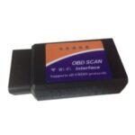
Lower-cost clones of the ELM327 have become widely accessible, often found on online marketplaces. These clones, available in USB, Bluetooth, Serial, and WiFi interfaces, offer an affordable entry point into vehicle diagnostics. These interfaces essentially virtualize a connection as a COM port, making them compatible with a wide range of computers and microcontrollers, including Arduino.
For Arduino users specifically, interfaces are available that provide TTL compatible serial data. This is where the arduino obd2 connector truly shines. These connectors are designed to directly interface with Arduino’s I/O pins, simplifying the connection process. By using a serial connection, Arduino enthusiasts can easily send commands to the ELM327 interface, query specific car parameters, store data, and display it as needed. Stanley, as mentioned in the original context, offers such an ELM327-compatible OBD-II interface specifically designed for direct connection to Arduino, complete with example code to get users started.
To effectively utilize the arduino obd2 connector and ELM327 interface, understanding AT commands and OBD “PID”s (Parameter IDs) is crucial. AT commands are used to control the ELM327 interface itself, allowing you to configure communication settings and initiate actions. OBD PIDs, on the other hand, are codes used to request specific data points from the vehicle’s ECU, such as engine temperature, speed, RPM, and much more. Resources like the Wikipedia page on OBD-II PIDs provide comprehensive lists of these parameters. Using a terminal program initially can be beneficial to familiarize yourself with basic AT commands like “ATI” to check the ELM327 version or “ATRV” to read the vehicle’s battery voltage directly through the arduino obd2 connector.
While the primary function of OBD2 and arduino obd2 connector setups is monitoring vehicle data in a “read-only” manner, it’s important to acknowledge the complexity of mimicking ECU communication. Attempting to emulate an ECU requires a deep understanding of the specific communication protocols used by different car manufacturers, including modulation schemes, handshakes, and error handling. These protocols are often complex and proprietary, making reverse engineering a significant challenge.
In conclusion, the arduino obd2 connector combined with an ELM327 interface provides a powerful and accessible platform for vehicle diagnostics and data acquisition. By understanding the basics of ELM327, AT commands, and OBD PIDs, users can leverage Arduino to create custom car monitoring systems, analyze vehicle performance, and gain valuable insights into their vehicle’s operation.