Are you fascinated by what goes on under the hood of your car? Imagine being able to peek into your car’s computer and understand its health, performance, and potential issues, all from your smartphone. With App Inventor 2 Obd2 and a simple ELM327 adapter, this is not just a dream but a tangible DIY project. This guide will walk you through the essentials of connecting your car’s On-Board Diagnostics (OBD2) system to an App Inventor 2 application, empowering you to create your own custom car diagnostic tool.
Understanding the Basics of OBD2 and ELM327 for App Inventor 2 Projects
Before diving into the app development, let’s clarify the key components. OBD2 (On-Board Diagnostics II) is a standardized system in most modern vehicles that provides access to various vehicle data. This data ranges from engine temperature and speed to diagnostic trouble codes (DTCs) that signal potential problems. To access this data, we use an ELM327 adapter. This small, inexpensive device plugs into your car’s OBD2 port and acts as a bridge, translating OBD2 protocols into data that can be transmitted wirelessly, typically via Bluetooth.
For our project, App Inventor 2 comes into play. This user-friendly, block-based programming platform from MIT allows even those without extensive coding knowledge to create Android applications. By combining App Inventor 2 with the ELM327, we can build a custom app to read and display real-time data from our car’s OBD2 system.
Setting Up the Connection: The Man-in-the-Middle Approach
One clever method to understand the communication between an OBD2 app and your car is to use a “man-in-the-middle” technique. This involves intercepting and analyzing the commands sent between an existing OBD2 app (readily available on app stores) and the ELM327 adapter.
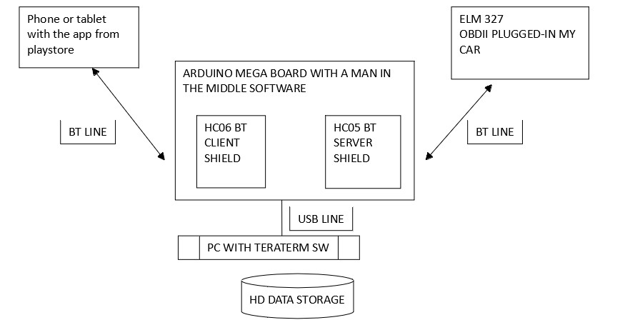
To achieve this, an Arduino setup can act as a sniffer. By placing the Arduino between your smartphone running an OBD2 app and the ELM327 connected to your car’s OBD2 port, you can monitor and record all communication.
This “man-in-the-middle” setup, as illustrated above, uses an Arduino Mega due to its multiple serial ports. The Arduino intercepts data transmitted between the smartphone and the ELM327, forwarding it to both devices and simultaneously to a computer for logging. By analyzing these logs, you can decipher the command sequences used to initiate communication with the car’s ECU (Engine Control Unit) and retrieve diagnostic information. This step, while not strictly necessary to build a basic app, is invaluable for understanding the underlying communication protocols and customizing your App Inventor 2 OBD2 project further.
Structuring Your App Inventor 2 OBD2 Application: Clock Timers and Bluetooth
A crucial aspect of creating an effective App Inventor 2 OBD2 app lies in managing data flow and timing. This is where Clock timers in App Inventor 2 become essential. The example application uses multiple clocks, each serving a specific purpose in the data acquisition and display process:
-
Clock1 (Data Reception): This clock is responsible for continuously listening for incoming data from the ELM327 via Bluetooth. It triggers procedures to process and display the received data, distinguishing between AT commands (ELM327 commands) and CAN data (car ECU data). Clock1 is enabled when a command is sent to the ELM327 and disabled upon receiving a valid response.
-
Clock2 (CAN Command Scheduler): To retrieve real-time data from the car, the app needs to periodically send CAN commands to the ECU. Clock2 acts as a scheduler, sending these commands at regular intervals. It starts after the initialization sequence (controlled by Clock4) and runs continuously until the user stops the data acquisition.
-
Clock3 (DTC Retrieval): Retrieving Diagnostic Trouble Codes (DTCs) is a key diagnostic function. Clock3 is dedicated to sending commands to the ELM327 to request DTCs from the car’s ECU. This clock ensures that the ECU has time to prepare the DTC data before it’s requested for display.
-
Clock4 (Initialization Sequence): Establishing communication with the car’s ECU requires a sequence of AT commands to initialize the ELM327 adapter and the CAN communication protocol. Clock4 is a scheduler that sends these AT commands in the correct order when the app starts. It disables itself once the initialization sequence is complete.
-
Clock5 (Real-time Clock Display): Purely for user interface enhancement, Clock5 updates a real-time clock display on the app screen, providing a visual indicator that the app is running.
This multi-clock structure allows for efficient and organized data handling in your App Inventor 2 OBD2 application.
Bluetooth Communication and Data Handling in App Inventor 2
The core communication between your App Inventor 2 OBD2 app and the ELM327 adapter happens via Bluetooth. The app initiates communication by sending a command to the ELM327 and then waits for a response. The receiving logic is designed to handle complete responses, which are typically terminated with a “>” character.
To ensure data integrity, the app continuously reads from the Bluetooth buffer until no new characters are received, clearing any residual data. Furthermore, when expecting a CAN data response, the app validates if the received data corresponds to the sent command. For instance, if the app sends a command to request engine speed (e.g., “01 0C”), it will only accept a response that starts with the corresponding service ID (e.g., “41 0C”). This simple validation mechanism ensures that the displayed data is accurate and relevant.
Designing Your App Interface in App Inventor 2
The user interface of your App Inventor 2 OBD2 app is crucial for displaying the retrieved car data effectively. A sample screen layout, as shown below, includes buttons to manually send specific commands and a “START” button to initiate the automatic data acquisition sequence.
This example interface features colored buttons for sending individual commands, mimicking the sequence used during the ELM327 initialization. The “START” button triggers the automatic command sequence, initiating communication with the car’s ECU. The interface also allows for selecting the CAN protocol, pre-set to KWP2000 @ 250 Kbps, which was suitable for the developer’s car. Users may need to adjust this setting based on their vehicle’s CAN protocol. The Bluetooth address for the ELM327 adapter is also configurable within the app.
Important considerations for interface design include:
- Clear Data Display: Use labels or similar components to display real-time data readings such as engine RPM, speed, temperature, and throttle position. Consider using visual elements like gauges or progress bars for enhanced readability.
- Command Buttons: Include buttons for sending common OBD2 commands, allowing users to manually request specific data or initiate diagnostic functions.
- Feedback Indicators: Provide visual feedback to the user, indicating connection status, data reception, and any errors that may occur.
Key App Inventor 2 Blocks for OBD2 Communication
Developing an App Inventor 2 OBD2 app involves using specific code blocks to handle Bluetooth communication, data parsing, and display updates. Here are some essential block categories and examples:
-
Bluetooth Client Blocks: These blocks are fundamental for establishing and managing Bluetooth connections with the ELM327 adapter. You’ll use blocks to:
- Connect to a Bluetooth device (using the ELM327’s Bluetooth address).
- Send text data (AT commands and CAN commands) via Bluetooth.
- Receive text data from Bluetooth.
- Check Bluetooth connection status.
-
Clock Timer Blocks: As discussed earlier, Clock timers are crucial for scheduling tasks and managing data flow. Blocks are used to:
- Enable and disable timers.
- Set timer intervals.
- Trigger events at specific intervals (e.g., sending CAN commands periodically).
-
Text Manipulation Blocks: OBD2 data is received as text strings. Text blocks are needed to:
- Parse and extract relevant data from the received strings.
- Format data for display.
- Compare strings (e.g., to validate responses).
-
List Blocks: Lists can be used to store sequences of commands (like the initialization sequence) or to manage data points.
-
UI Component Blocks: Blocks for interacting with user interface elements like labels, buttons, and potentially more advanced components for data visualization.
The following images showcase examples of App Inventor 2 blocks used in the example OBD2 application:
General overview of code blocks structure.
Example of Clock1 Timer blocks for data receiving and processing.
Example of blocks for the “START” button click event, initiating the initialization sequence.
By understanding and utilizing these block categories, you can construct the logic for your own App Inventor 2 OBD2 application.
Conclusion: Empowering DIY Car Diagnostics with App Inventor 2
This guide provides a foundational understanding of how to create an App Inventor 2 OBD2 application for car diagnostics using an ELM327 adapter. While the example code is not a complete, ready-to-use app, it serves as a valuable starting point and demonstrates the core principles of OBD2 communication within the App Inventor 2 environment.
Building your own car diagnostic tool is not only a rewarding DIY project but also a fantastic way to learn about automotive technology and mobile app development. You can expand upon this foundation by:
- Implementing more OBD2 commands to retrieve a wider range of car data.
- Adding features to decode and display Diagnostic Trouble Codes (DTCs) in a user-friendly format.
- Developing more sophisticated data visualization techniques to present car performance information effectively.
- Contributing to the growing community of DIY car enthusiasts and App Inventor developers.
With App Inventor 2 OBD2 projects, the possibilities are vast, limited only by your curiosity and willingness to explore the fascinating intersection of software and automotive engineering.