Understanding the On-Board Diagnostics (OBD2) system in vehicles is crucial for anyone involved in automotive repair, diagnostics, or data analysis. While OBD2 is standardized, variations exist, particularly when it comes to voltage and connector types in different vehicle categories. This guide provides a detailed look at the 24 Volt Obd2 Data Link Connector Pins, focusing on their specific applications, pinout configurations, and how they differ from the more common 12 volt systems.
This article expands on the fundamentals of OBD2, delving into the specifics of 24V systems, which are frequently found in trucks, buses, and heavy-duty vehicles. We will clarify the pin assignments of the 24 volt OBD2 connector, its role in vehicle diagnostics, and provide practical insights for working with these systems.
Alt text: Malfunction Indicator Light (MIL) illuminating on a dashboard, indicating an OBD2 system issue requiring a scan tool for diagnostics.
OBD2 and Voltage: Understanding 12V vs 24V Systems
The OBD2 system is designed to monitor and report on a vehicle’s health, particularly concerning emissions and engine performance. It achieves this through a standardized connector, the Data Link Connector (DLC), which allows diagnostic tools to interface with the vehicle’s electronic control units (ECUs).
Most passenger cars and light-duty vehicles operate on a 12 volt electrical system, and their OBD2 connectors are designed accordingly. However, a significant class of vehicles, including commercial trucks, buses, and heavy machinery, utilizes 24 volt electrical systems. These 24V systems necessitate variations in the OBD2 connector, primarily in terms of power supply, to ensure compatibility and safety.
While the OBD2 protocol itself remains largely consistent across both 12V and 24V systems, understanding the nuances of the 24 volt OBD2 data link connector pins is essential for technicians and engineers working with these heavier vehicles.
Does Your Vehicle Use a 24 Volt OBD2 Connector?
Determining if a vehicle uses a 24 volt OBD2 system is generally straightforward. The vehicle type is the most reliable indicator:
-
24V OBD2 Systems: Typically found in:
- Heavy-duty trucks (Class 6, 7, 8)
- Buses and coaches
- Some commercial vans and RVs
- Construction and agricultural equipment
-
12V OBD2 Systems: Predominantly used in:
- Passenger cars
- Light-duty trucks and SUVs
- Minivans
Visually, the OBD2 connector itself might appear similar in both 12V and 24V applications, as both adhere to the SAE J1962 standard in terms of pin count and basic layout. However, the type of OBD2 connector (Type A or Type B) and the voltage supplied to pin 16 are the key differentiating factors.
Alt text: Chart illustrating OBD2 compliance timeline for vehicles in EU and US based on vehicle type and purchase year, indicating when OBD2 became mandatory.
The OBD2 Connector: Type A vs. Type B and 24 Volt Specifications
The SAE J1962 standard defines two main types of OBD2 connectors: Type A and Type B. These types are critical when discussing 24 volt OBD2 data link connector pins because Type B is specifically designed to accommodate 24V systems.
OBD2 Connector Type A:
- Standard for passenger cars and light-duty vehicles (12V systems).
- Provides 12V power supply on pin 16.
- Rectangular shape with a single groove.
OBD2 Connector Type B:
- Common in medium and heavy-duty vehicles (24V systems).
- Provides 24V power supply on pin 16.
- Visually distinct with an interrupted groove in the middle, allowing Type B adapters to fit both Type A and B sockets, but Type A adapters only fit Type A sockets.
The key difference relevant to 24 volt OBD2 data link connector pins lies in pin 16, which is the battery power pin. In a Type A connector, this pin typically outputs 12V, whereas in a Type B connector, it outputs 24V. This voltage difference is crucial for powering OBD2 diagnostic tools and ensuring they are compatible with the vehicle’s electrical system.
Alt text: Diagram contrasting OBD2 Connector Type A and Type B, highlighting the interrupted groove in Type B, and indicating 12V for Type A (car/van) and 24V for Type B (truck).
24 Volt OBD2 Data Link Connector Pinout: Detailed Breakdown
The pinout of the OBD2 connector, whether Type A or Type B, is largely standardized by SAE J1962. Understanding each pin’s function is vital when working with 24 volt OBD2 data link connector pins for diagnostics and data acquisition.
Here’s a detailed breakdown of the OBD2 connector pinout, applicable to both 12V and 24V systems, with specific notes on voltage considerations for 24V:
| Pin Number | Pin Name | Function | Notes for 24V Systems |
|---|---|---|---|
| 1 | Manufacturer Discretionary | Varies by manufacturer; often used for OEM-specific diagnostics. | Function may be manufacturer-specific, consistent in 24V vehicles of the same brand. |
| 2 | J1850 Bus+ | SAE J1850 VPW and PWM bus positive line (older Ford/GM protocols). | Typically not used in modern 24V CAN-based systems, but may be present in older heavy-duty vehicles using J1850 protocols. |
| 3 | Manufacturer Discretionary | Varies by manufacturer; often used for OEM-specific diagnostics or grounds. | Function may be manufacturer-specific, consistent in 24V vehicles of the same brand. |
| 4 | Chassis Ground | Ground connection for the vehicle chassis. | Crucial ground reference for diagnostic tools in 24V systems. |
| 5 | Signal Ground | Signal ground reference for ECU communication. | Ensures stable signal transmission in potentially noisy 24V electrical environments. |
| 6 | CAN High (CAN-H) | CAN bus high signal line (ISO 15765-4). | Standard CAN High for communication in 24V systems using CAN protocol. |
| 7 | K-Line (ISO 9141-2 & ISO 14230-4) | K-line for ISO 9141-2 and ISO 14230-4 (KWP2000) protocols (older protocols). | Less common in modern 24V systems primarily utilizing CAN, but may be found in older models. |
| 8 | Manufacturer Discretionary | Varies by manufacturer; often used for OEM-specific diagnostics. | Function may be manufacturer-specific, consistent in 24V vehicles of the same brand. |
| 9 | Manufacturer Discretionary | Varies by manufacturer; often used for OEM-specific diagnostics. | Function may be manufacturer-specific, consistent in 24V vehicles of the same brand. |
| 10 | J1850 Bus- | SAE J1850 VPW and PWM bus negative line (older Ford/GM protocols). | Typically not used in modern 24V CAN-based systems, similar to pin 2. |
| 11 | Manufacturer Discretionary | Varies by manufacturer; often used for OEM-specific diagnostics. | Function may be manufacturer-specific, consistent in 24V vehicles of the same brand. |
| 12 | Manufacturer Discretionary | Varies by manufacturer; often used for OEM-specific diagnostics. | Function may be manufacturer-specific, consistent in 24V vehicles of the same brand. |
| 13 | Manufacturer Discretionary | Varies by manufacturer; often used for OEM-specific diagnostics. | Function may be manufacturer-specific, consistent in 24V vehicles of the same brand. |
| 14 | CAN Low (CAN-L) | CAN bus low signal line (ISO 15765-4). | Standard CAN Low for communication in 24V systems using CAN protocol. |
| 15 | L-Line (ISO 9141-2 & ISO 14230-4) | L-line for ISO 9141-2 and ISO 14230-4 (KWP2000) protocols (older protocols). | Less common in modern 24V systems, similar to pin 7. |
| 16 | Battery Power | Vehicle battery positive voltage supply to the scan tool. | Crucially provides 24V in Type B connectors, essential for powering tools designed for 24V systems. Using a 12V tool on a 24V system via this pin can damage the tool. |

Alt text: OBD2 Connector Pinout diagram, illustrating pin numbers 1 through 16 in a female Type A Data Link Connector (DLC) socket.
Key Considerations for 24 Volt OBD2 Systems:
- Pin 16 Voltage: Always verify that your diagnostic tool is rated for 24V input before connecting to a 24 volt OBD2 data link connector. Using a 12V tool on a 24V system can cause immediate damage.
- Ground Pins (4 & 5): Ensure robust ground connections. 24V systems can sometimes experience higher levels of electrical noise, making good grounding critical for reliable data communication.
- CAN Bus Pins (6 & 14): These pins are the primary channels for OBD2 communication in modern 24V vehicles, which predominantly use CAN (ISO 15765-4) as the lower-layer protocol.
OBD2 Protocols in 24 Volt Systems
While the physical connector and voltage supply might differ, the OBD2 communication protocols used in 24V systems are generally consistent with those in 12V systems. The most common protocols you’ll encounter in modern 24V OBD2 applications are:
- ISO 15765-4 (CAN): Dominant protocol in vehicles manufactured after 2008 and widely used in heavy-duty and commercial vehicles. 24 volt OBD2 data link connector pins 6 (CAN-H) and 14 (CAN-L) are active in these systems.
- ISO 14230-4 (KWP2000): Keyword Protocol 2000, an older protocol, but may still be found in some pre-2008 24V vehicles. Pin 7 (K-Line) is used.
- ISO 9141-2: Another older protocol, less common in 24V applications but potentially present in older systems. Pins 7 (K-Line) and 15 (L-Line) are used.
- SAE J1850 (VPW & PWM): Protocols primarily used in older American-made vehicles (GM and Ford respectively). Less likely to be encountered in 24V systems, but possible in some older heavy trucks. Pins 2 (J1850 Bus+) and 10 (J1850 Bus-) are used.
Alt text: Diagram illustrating the five main OBD2 protocols: CAN (ISO 15765), KWP2000 (ISO 14230-4), ISO 9141, SAE J1850 VPW, and SAE J1850 PWM, highlighting CAN as the dominant modern standard.
In most modern 24V trucks and buses, CAN bus via pins 6 and 14 of the 24 volt OBD2 data link connector is the standard communication method. Therefore, diagnostic tools focusing on CAN protocol are generally well-suited for these vehicles.
Practical Considerations When Working with 24 Volt OBD2 Systems
Working with 24 volt OBD2 data link connector pins requires some specific considerations compared to 12V systems:
-
Tool Compatibility: Always ensure your OBD2 scanner, data logger, or interface is rated for 24V input. Many standard automotive OBD2 tools are designed only for 12V. Using a 12V tool on a 24V system can lead to electrical damage and tool malfunction. Look for tools specifically labeled as “12V/24V compatible” or “heavy-duty OBD2 scanners.”
-
Connector Type Verification: Before connecting any tool, visually inspect the OBD2 connector in the vehicle. If it’s a Type B connector (with the interrupted groove), it is highly likely to be a 24V system. However, always double-check vehicle documentation if unsure.
-
Adapter Cables: If you need to connect a standard Type A OBD2 tool to a Type B socket, use a Type B to Type A adapter cable. Ensure the adapter is also rated for 24V if applicable and does not inadvertently step down the voltage if the tool is 24V compatible. For 12V-only tools, voltage step-down adapters might be needed, but use these with caution and verify compatibility thoroughly.
-
Diagnostic Procedures: The fundamental OBD2 diagnostic procedures (reading DTCs, accessing PIDs, etc.) are the same for both 12V and 24V systems. However, some heavy-duty vehicles may have additional proprietary diagnostic codes and parameters beyond the standard OBD2 set.
-
Data Logging in 24V Vehicles: When using OBD2 data loggers in 24V vehicles, power the logger appropriately from the 24 volt OBD2 data link connector pin 16 if the logger is designed for 24V. Ensure the logger’s CAN interface is compatible with the vehicle’s CAN bus speed (typically 250Kbps or 500Kbps in heavy-duty applications).
Alt text: Diagram illustrating OBD2 data logging setup, showing a data logger connected to the OBD2 port requesting PID data using CAN IDs 7DF (request) and 7E8 (response).
Conclusion: Mastering the 24 Volt OBD2 Data Link Connector
Understanding the specifics of the 24 volt OBD2 data link connector pins is crucial for anyone working with heavy-duty vehicles. While the OBD2 standard provides a common framework, the voltage difference and connector types (Type A vs. Type B) are important distinctions. Always verify tool compatibility with 24V systems and be mindful of the pinout, particularly pin 16 (battery power), to avoid damage and ensure accurate diagnostics.
By mastering these details, technicians and engineers can effectively diagnose, monitor, and extract data from the growing number of 24V OBD2 equipped vehicles on the road today.
For further learning, explore our comprehensive guides on CAN bus, OBD2 protocols, and data logging solutions.
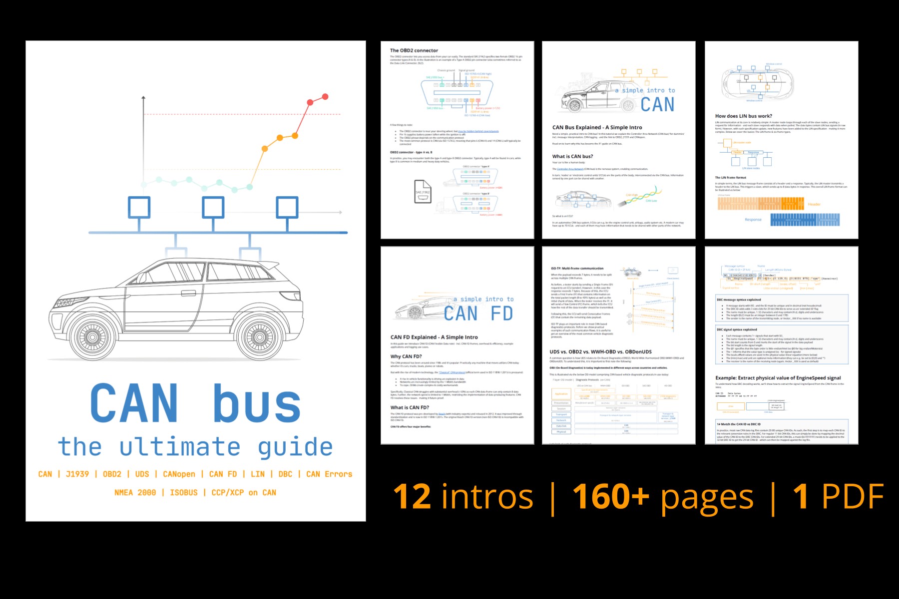
Get our ‘Ultimate CAN Guide’
Want to become a CAN bus expert?
Get our 12 ‘simple intros’ in one 160+ page PDF:
Download now
Alt text: Cover image for the “Ultimate CAN Bus Guide” PDF, promoting a comprehensive tutorial on CAN bus technology.