The accelerator pedal position (APP) sensor is a crucial component in modern vehicles, especially those with drive-by-wire throttle systems. This sensor tells your car’s Engine Control Unit (ECU) how much you want to accelerate. To ensure accuracy and safety, APP sensors are designed with redundancy in mind, typically incorporating multiple sensors within a single unit. This article delves into the workings of these sensors, their diagnostic aspects accessible via OBD2, and what it means for your vehicle’s performance.
Modern APP sensors commonly integrate two or more individual sensors to validate signal integrity. For fail-safe operation, the ECU supplies these sensors with distinct voltage sources. A common configuration involves one sensor, often referred to as sensor E, receiving half the input voltage compared to another sensor, sensor D. This difference in input voltage results in a proportional difference in their output voltage readings.
Research indicates that most APP sensors operate on an incremental voltage principle, similar to throttle position sensors. As you depress the accelerator pedal further, the voltage signal sent to the ECU increases. Because of the dual-sensor design with differing voltage supplies, the ECU can constantly cross-reference the readings to verify sensor accuracy. The ECU expects a consistent relationship between these sensor readings. In many vehicles, an algorithm like “Sensor E voltage X 2 = Sensor D voltage” is applied. For instance, if sensor E reads 1.5 volts, sensor D should ideally read approximately 3 volts, with a tolerance usually around ±50 mV.
This ingenious design allows the ECU to immediately detect discrepancies and potential faults within the APP sensor circuit. If one sensor malfunctions, the voltage difference between sensor E and sensor D will exceed the acceptable threshold, generally around 100mV or more. When such a deviation is detected, the ECU recognizes a sensor disagreement despite them being in the same physical position. In drive-by-wire systems, where the accelerator pedal directly controls the throttle electronically, a faulty APP sensor can trigger a safety mechanism. The ECU will often activate a limp-mode, restricting engine power and speed, and simultaneously illuminate warning lights on your dashboard. Furthermore, Diagnostic Trouble Codes (DTCs) will be stored, accessible via an OBD2 scanner, to pinpoint the issue for technicians.
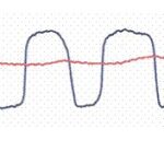
When using an OBD2 data logger, it’s important to understand how your specific tool displays APP sensor readings. You might observe one sensor reading reaching 100% at full pedal depression while another peaks at 50%. While it’s often speculated that sensor D reflects the actual pedal position, it’s advisable to test this in your vehicle by fully depressing the accelerator and observing which sensor value maxes out.
It’s crucial to remember that the accelerator pedal position is distinct from the actual throttle position commanded by the ECU. The ECU calculates the desired throttle opening based on various factors beyond pedal input, including driving modes (e.g., sport, eco), cruise control settings, and engine load. OBD2 data often provides both “Relative Throttle Position” and “Absolute Throttle Position” parameters. Relative throttle position typically represents a 0-100% range reflecting the ECU’s commanded throttle opening, while Absolute throttle position might include the idle position where the throttle plate is slightly open even at rest, potentially showing a slightly higher minimum value depending on the engine design. Understanding these distinctions is key to accurate diagnostics when investigating engine performance issues using OBD2 data related to accelerator and throttle systems.