For 1G DSM (Diamond Star Motors) enthusiasts looking to enhance their vehicle’s engine management system, swapping to a 2G ECU (Engine Control Unit) offers significant advantages. This upgrade not only unlocks the potential for advanced tuning capabilities, particularly with systems like ECMlink, but also brings the convenience of OBD2 (On-Board Diagnostics II) connectivity. This guide provides a detailed walkthrough on how to perform the necessary wiring modifications, focusing on the 2g Dsm Obd2 Pinout, to successfully integrate a 2G ECU and OBD2 port into your 1G DSM.
What You’ll Need for the 2G DSM OBD2 Pinout Conversion
Before starting this conversion, ensure you have gathered all the necessary tools and components. This meticulous process requires precision and patience, so proper preparation is key. Here’s a list of what you will need:
- Soldering Gun: For creating secure and lasting electrical connections.
- Solder Sucker or Wick: To remove solder effectively, especially when working with the delicate ECU pins.
- Shrink Wrap Tubing: Essential for insulating soldered connections, preventing shorts, and ensuring a clean, professional finish.
- Wire Strippers: To precisely strip wire insulation without damaging the conductors.
- Extra Wire: Various colors are helpful for organization, but ensure it’s of appropriate gauge for automotive applications.
- Spare 1G ECU: Ideally, a non-working or “fried” ECU is recommended. This will be sacrificed to salvage its connector plug.
- 2G Interior Harness: This is crucial for obtaining the OBD2 port and its connector.
- 2G Engine Harness: You will need the ECU plugs from the 2G engine harness.
- Patience: This conversion requires careful work and attention to detail. Rushing can lead to errors and potential damage.
Step-by-Step Guide to 2G DSM OBD2 Pinout Conversion
Step 1: Prepare the 1G ECU Plug
Begin by taking your spare 1G ECU. The goal here is to carefully remove the connector plug from the ECU board. This plug will be essential for adapting the 2G wiring to your 1G’s electrical system.
Using your soldering gun and solder sucker or wick, gently desolder the pins of the connector from the 1G ECU board. Take your time with this step. The longer you can keep the pins intact during desoldering, the better contact and stronger solder joints you will achieve later. Work methodically to avoid damaging the plastic housing of the connector.
Step 2: Prepare the 2G Harnesses
Next, take your 2G engine harness and locate the ECU plugs. Cut these plugs off the harness, leaving approximately 6-8 inches of wire attached to each plug. This extra wire provides ample room to work with during the soldering process.
Similarly, take your 2G interior harness and locate the OBD2 port. Cut the OBD2 port connector off the harness, again leaving a generous length of wire attached.
Step 3: Understanding the Pinouts – The Key to Success
This step is arguably the most critical. Before proceeding any further, thoroughly review the 1G and 2G ECU pinouts. Understanding the pinout diagrams is paramount to ensuring correct wiring and preventing damage to your ECUs or vehicle.
The following diagrams illustrate the 2G pinouts with the corresponding 1G pinouts overlaid in RED. Pay very close attention to the orientation of the pinouts as presented in these diagrams to avoid mirroring or misinterpreting the pin locations.
Image 1: Diagram showing the first part of the 2G DSM ECU pinout with 1G DSM pinout overlayed in red for comparison.
Image 2: Diagram showing the second part of the 2G DSM ECU pinout with 1G DSM pinout overlayed in red for comparison.
Step 4: Soldering and Wiring – One Pin at a Time
Now, begin the process of soldering the wires from the 2G ECU plugs to the 1G ECU connector pins that you prepared in Step 1. Work one wire at a time to minimize confusion and errors.
Crucially, do not forget to slide a piece of shrink wrap tubing onto each wire before you make the solder connection. This step is easily overlooked but essential for insulating each connection later.
When soldering, focus on the pinouts, not the wire colors. Wire colors may not always match between the 1G and 2G harnesses. Refer to your pinout diagrams to ensure you are connecting the correct pins to each other, regardless of wire color.
For optimal soldering on the delicate 1G connector pins, consider using the “tinning” method. Prolonged heat from the soldering gun directly on the 1G pins can melt the plastic housing and loosen the pins. Instead, tin both the wire end and the 1G connector pin with a small amount of solder separately. Allow them to cool slightly, then quickly reheat both tinned surfaces and join them together. This method minimizes heat transfer to the plastic connector.
Step 5: Wiring Completion Check
After soldering a significant portion of the wires, you should reach a stage visually similar to the image below. If your work resembles this, congratulations! You’re well on your way to completing the conversion. Continue this process, meticulously soldering each wire according to the pinout diagrams until all necessary connections are made. Once all wires are soldered, slide the shrink wrap tubing over each connection and use a heat gun (or gentle heat source) to shrink the tubing, securely insulating each solder joint.
Image 3: Example of the wiring progress during a 2G to 1G ECU conversion, highlighting soldered connections and heat shrink tubing.
Step 6: Wiring the OBD2 Port
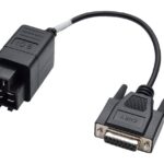
Now, you need to wire the OBD2 port. This involves soldering four wires from your converted harness to the OBD2 connector you obtained from the 2G interior harness. For the specific pinouts for the OBD2 port wiring, refer to the ECMlink wiki, which provides detailed and accurate information.
https://www.ecmtuning.com/wiki/connectionproblem
Consider the placement of your OBD2 port. A common location is within the plastic spacer underneath the dashboard, providing a discreet yet accessible location. You may need to lengthen the wires from the OBD2 connector to reach your desired mounting point. Solder and insulate these connections as you did with the ECU wiring.
Step 7: ECU Installation
With the wiring complete, you should now be ready to install your 2G ECU into your 1G DSM! Carefully plug in your newly converted ECU harness into the 2G ECU.
Image 4: A 2G ECU successfully installed in a 1G DSM vehicle following the OBD2 pinout conversion.
Step 8: Ignition Firing Order – Critical!
It is absolutely essential to use a 2G ignition firing order after this conversion. The 2G ECU operates with a different firing order than the 1G. Ensure your engine management settings and any aftermarket systems are configured to the 2G firing order to prevent engine damage and ensure proper operation.
Step 9: Testing and Troubleshooting
Turn your ignition to the “forward” or “ON” position and attempt to connect to the ECU using ECMlink or your chosen diagnostic software. If you establish a connection, great! Initiate a live data capture and gently manipulate the throttle to verify that the throttle position sensor (TPS) is reading correctly.
If you cannot connect to the ECU, or if readings are incorrect, carefully re-examine your wiring. Double-check every soldered connection against the pinout diagrams from Step 3. Wiring errors are the most common cause of issues at this stage.
Step 10: Enjoy the OBD2 Upgrade!
If everything checks out, congratulations! You have successfully upgraded your 1G DSM with a 2G ECU and functional OBD2 port. You can now enjoy the benefits of enhanced engine management capabilities and modern diagnostic access.
This conversion is a testament to the ingenuity and resourcefulness of the DSM community. Special thanks to the following individuals who contributed to the knowledge and techniques that made this guide possible:
- Slowcon (ecmlink)
- Junfan (dsmtuners)
- Hal (dsmtuners)
By following these steps carefully and paying close attention to detail, you can bring the advantages of a 2G ECU and OBD2 diagnostics to your 1G DSM, unlocking a new level of tuning and monitoring potential for your vehicle. Remember to always prioritize safety and double-check your work throughout the process.