Are you struggling to get your Arduino CAN shield to communicate with your car’s OBD2 port? Many makers and car enthusiasts dive into projects requiring real-time vehicle data, such as custom instrument clusters or performance monitoring systems. A common hurdle is establishing a reliable connection between an Arduino and a car’s Controller Area Network (CAN bus) via the OBD2 port using a CAN shield. If you’re facing issues where your setup isn’t reading data like engine RPM or vehicle speed, and even basic test sketches fail, you’re not alone. This guide will walk you through common problems and troubleshooting steps to get your Arduino CAN shield and OBD2 connection working smoothly.
Understanding the OBD2 CAN Bus Challenge
Connecting an Arduino with a CAN shield to your car’s OBD2 port seems straightforward, but several factors can lead to communication breakdowns. One user encountered this exact problem with a Seeed CAN Shield V2.0, experiencing continuous data “spamming” and no response to OBD2 requests. Even after trying example codes designed for OBD2 data retrieval, they hit a wall. Let’s break down the potential culprits and how to address them.
The user described a situation where, even with simple send commands, the CAN shield appeared to constantly transmit data without pauses, as seen on their oscilloscope. This behavior raises questions about whether the shield is functioning correctly, if the code is properly configured, or if there’s a fundamental issue in the connection to the OBD2 port. They also confirmed the OBD2 port itself was working with a standard OBD2 scanner, ruling out a car-side problem.
Diagnosing Common Issues
Let’s explore the most frequent reasons why your Arduino CAN shield might fail to communicate with your car’s OBD2 port.
1. Wiring and Connection Problems
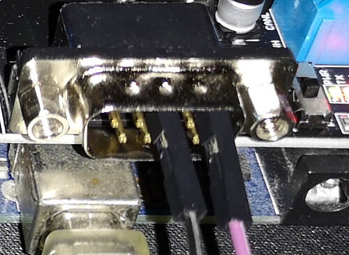
The physical connection is the foundation of any successful communication. Incorrect wiring is a prime suspect when facing OBD2 connection issues. The user in question meticulously crafted their OBD2 to DB9 cable, referencing multiple sources and verifying with a multimeter. However, even with careful wiring, mistakes can happen, or there might be subtle issues.
- OBD2 Cable Integrity: Double-check your OBD2 cable wiring against reliable diagrams. Ensure each pin is correctly connected to the corresponding pin on your DB9 connector and subsequently to the CAN shield. Pay close attention to CAN High and CAN Low wires, as swapping them will prevent communication.
- Secure Connections: Make sure all connections are firm and secure. Loose wires can cause intermittent communication or complete signal loss.
- Power and Ground: Verify that the CAN shield and Arduino are properly powered and grounded. A stable power supply is crucial for reliable CAN communication.
2. Code and Library Configuration
Software misconfiguration is another common pitfall. Even with correct wiring, your Arduino code and CAN library settings must be properly aligned for OBD2 communication.
- CAN Bus Speed: OBD2 CAN bus typically operates at 500 kbps. Ensure your Arduino code initializes the CAN bus at this speed. Incorrect baud rate settings will prevent successful data exchange.
- CAN Library Compatibility: Confirm that the CAN library you are using (e.g.,
mcp_can.hfor MCP2515-based shields like the Seeed CAN Shield V2.0) is correctly installed and compatible with your Arduino board and CAN shield. - Shield Chip Select (CS) Pin: The Chip Select (CS) pin for the SPI communication with the MCP2515 CAN controller must be correctly defined in your code, matching the physical connection on your Arduino and shield. For the Seeed CAN Shield V2.0, the CS pin is often D9, but verify your shield’s documentation.
- OBD2 PID Requests: OBD2 communication relies on sending specific Parameter IDs (PIDs) to request data. The example code provided by the user attempts to request engine RPM (PID 0x0C) and vehicle speed (PID 0x0D). Ensure your code is sending valid OBD2 PID requests in the correct format.
- CAN Filters and Masks: While not always necessary for basic OBD2 communication, incorrect CAN filter and mask settings can prevent your shield from receiving responses from the car’s ECU. In the provided code, filters are set to receive messages from
RESP_MSG(0x7E8), which is a common response ID for OBD2 requests. Double-check these settings if you suspect filtering issues.
3. Shield Hardware Issues
While less frequent, a faulty CAN shield can also be the source of the problem. Since the user only had one shield, they couldn’t definitively rule out a hardware malfunction.
- Shield Testing: If possible, try testing your CAN shield with another CAN bus device or network to verify its basic functionality. If you have access to another CAN shield, swapping them can help isolate a hardware problem.
- Visual Inspection: Carefully inspect the CAN shield for any visible damage, such as broken components, bent pins, or soldering issues.
4. CAN Bus Termination
For reliable CAN bus communication, proper termination is essential, especially in longer bus setups. However, for simple OBD2 connections within a car, termination is usually handled by the vehicle’s internal CAN bus network. In most cases, you won’t need to add external termination resistors when connecting directly to the OBD2 port. But, if you are extending the CAN bus wiring significantly or experiencing persistent communication errors, checking termination might be necessary.
Reviewing Example Code and Sketches
The user tried both the Seeed Studio example code and another code snippet found online. Let’s briefly analyze these.
The Seeed Studio example OBDII_PIDs is a good starting point, designed to request and display OBD2 data. The user’s modified code attempts to automate PID requests for RPM and speed. The key parts of this code to verify are:
- CAN Bus Initialization:
CAN.begin(CAN_500KBPS)must correctly set the baud rate to 500 kbps. - Filters and Masks: The filters are set to receive responses from
RESP_MSG(0x7E8). - PID Request Function
sendPid(): This function constructs the CAN message to request a specific PID. The data bytes are formatted according to OBD2 standards. - Data Reception
taskCanRecv(): This function checks for incoming CAN messages and attempts to read and display the received data.
The second code example, using U8glib for OLED display, is functionally similar in terms of CAN communication but integrates with an OLED screen for data output. The OBD2 request function obd2Request() is similar to the sendPid() function in the first example.
Step-by-Step Troubleshooting Guide
- Verify Wiring: Meticulously re-check your OBD2 cable wiring and all connections to the CAN shield and Arduino. Use a multimeter to confirm continuity and correct pin assignments.
- Code Review: Carefully examine your Arduino code, paying close attention to CAN bus initialization, baud rate, CS pin definition, CAN library inclusion, and OBD2 PID request formatting.
- Example Code Test: Start with the basic example code provided by Seeed Studio for your CAN shield. If this example fails, it points to a fundamental wiring or hardware issue.
- Simplify and Isolate: Reduce your code to the bare minimum needed to send a single OBD2 PID request and receive a response. This helps isolate the problem.
- Oscilloscope Analysis: If you have access to an oscilloscope, examine the CAN bus signals. This can help identify signal integrity issues, noise, or incorrect transmission patterns. The user’s oscilloscope output showing continuous transmission is a valuable clue. It might indicate a problem with the CAN shield’s transmit functionality or a code loop issue.
- Shield Swap (If Possible): If you can obtain another CAN shield, try swapping it into your setup to rule out a hardware defect in the original shield.
- Community Support: Reach out to online communities, forums, or the manufacturer’s support channels for your CAN shield. Often, other users have encountered similar issues and can offer valuable insights.
Moving Forward with Your OBD2 Project
Getting your Arduino CAN shield to interface with OBD2 opens up a world of possibilities for car customization and data analysis. While troubleshooting connection issues can be frustrating, systematically checking each potential point of failure – wiring, code, hardware – will lead you to a solution. Remember to double-check every step, utilize available example code and resources, and don’t hesitate to seek help from the maker community. With persistence and careful diagnosis, you’ll be reading live data from your car’s CAN bus in no time and progressing with your exciting automotive projects.