Maintaining your 2007-2012 Hyundai Santa Fe in peak condition requires understanding its electrical system, and a crucial part of that is the fuse box. Fuses protect your vehicle’s electrical circuits from overloads, preventing potential damage and costly repairs. This comprehensive guide provides you with detailed fuse box diagrams for your Hyundai Santa Fe (CM) manufactured between 2007 and 2012. Whether you’re dealing with a blown fuse or simply performing routine maintenance, knowing the fuse layout is essential.
Locating the Fuse Boxes in Your Hyundai Santa Fe
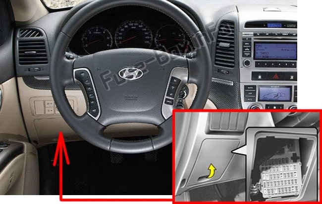
Your Hyundai Santa Fe (CM) has two main fuse box locations: the instrument panel and the engine compartment.
Instrument Panel Fuse Box
The instrument panel fuse box, also known as the interior fuse box, is conveniently located inside the passenger compartment. Specifically, it’s situated on the driver’s side, behind a protective cover. Accessing this fuse box is usually straightforward and doesn’t require any tools.
Engine Compartment Fuse Box
The second fuse box is located in the engine compartment, typically on the left-hand side when facing the engine. This box houses fuses and relays that protect circuits related to the engine, powertrain, and other critical vehicle systems.
Inside both the instrument panel and engine compartment fuse boxes, you’ll find a label on the cover. This label provides a diagram and a list of fuse and relay assignments, indicating what each fuse protects and its amperage rating. Always refer to the label inside your specific vehicle’s fuse box, as there might be slight variations depending on the model year and installed options.
Hyundai Santa Fe Fuse Box Diagrams: 2007-2009
For Hyundai Santa Fe models manufactured in 2007, 2008, and 2009, the fuse layouts are consistent. Below are the diagrams and corresponding fuse assignment tables for both the instrument panel and engine compartment fuse boxes.
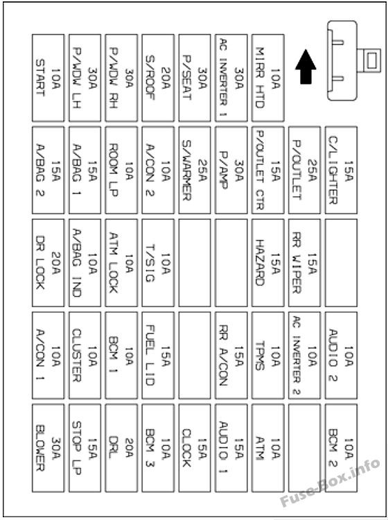
Instrument Panel Fuse Diagram (2007-2009)
Instrument Panel Fuse Assignment (2007, 2008, 2009)
| Fuse Number | Name | AMP Rating | Circuit Protected |
|---|---|---|---|
| C/LIGHTER | 15A | Cigarette Lighter | |
| P/OUTLET | 25A | Front Power Outlet, Rear Power Outlet | |
| P/OUTLET CTR | 15A | Center Power Outlet | |
| AUDIO #2 | 10A | Power Outside Mirror Switch, Audio, ATM Key Lock Control Module, Digital Clock | |
| RR WIPER | 15A | Multifunction Switch, Rear Wiper Control Module, Rear Wiper Motor | |
| IMS | 10A | Rain Sensor | |
| BCM #2 | 10A | Rheostat, BCM, Instrument Cluster | |
| A/CON2 | 10A | A/C Control Module, Incar & Humidity Sensor, High Blower Relay, Rear A/CON Switch, ICM Relay Box, AQS Sensor, Sunroof Motor, Blower Relay, Electro Chromic Mirror | |
| BLOWER | 30A | Blower Relay, Blower Motor, A/C Control Module | |
| A/CON1 | 10A | A/C Control Module | |
| A/BAG #1 | 15A | SRS Control Module | |
| A/BAGIND | 10A | PAB ON/OFF Switch, Instrument Cluster | |
| T/SIG | 10A | Hazard Switch | |
| ATM LOCK | 10A | Multifunction Switch, Steering Angle Sensor, ESC Switch, ATM Key Lock Control Module Seat Warmer Module | |
| BCM #1 | 10A | Oil Level Sensor Module, BCM | |
| CLUSTER | 10A | Instrument Cluster, Pre-Excitation Resistor, BCM, Generator, Semi Active Control Module (Gasoline) | |
| START | 10A | Burglar Alarm Relay | |
| P/AMP | 30A | Delphi Amp | |
| S/WARMER | 25A | Seat Warmer Control Module | |
| P/SEAT | 30A | Power Seat Switch | |
| RRA/CON | 15A | ICM Relay Box | |
| RR FOG/BWS | 10A | ICM Relay Box | |
| S/ROOF | 20A | Sunroof Motor | |
| MIRRHTD | 10A | Rear Defogger Switch, Power Outside Mirror Motor | |
| DFVLOCK | 20A | Door Lock (UN) Relay, ICM Relay Box | |
| STOP LP | 15A | Stop Lamp Switch | |
| FUEL LID | 15A | Fuel Lid Switch | |
| ATM | 10A | Key Solenoid, Sports Mode Switch, Semi Active Solenoid (Gasoline) Instrument Cluster, Luggage Lamp, Map Lamp, Rear Personal Lamp, | |
| ROOM LP | 10A | Room Lamp, Front Door Lamp Cargo Lamp, Vanity Lamp Switch | |
| BCM #3 | 10A | Door Warning Switch, BCM, Security Indicator | |
| CLOCK | 15A | A/C Control Module, Data Link Connector, Digital Clock | |
| AUDIO #1 | 15A | Delphi Audio | |
| HAZARD | 15A | Hazard Switch, Hazard Relay | |
| P/WDWLH | 30A | Power Window Main Switch, Rear Power Window Switch LH | |
| P/WDWRH | 30A | Power Window Main Switch, Rear Power Window Switch RH | |
| AC INVERTER 1 | 30A | AC Inverter | |
| AC INVERTER2 | 10A | AC Inverter | |
| TPMS | 10A | Tire Pressure Monitoring System | |
| A/BAG2 | 15A | Airbag | |
| T/SIG | 10A | Turn Signal Light | |
| DRL | 20A | Daytime Running Light (If Installed) |
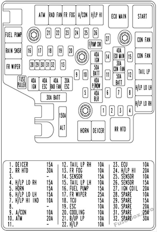
Engine Compartment Fuse Diagram (2007-2009)
Engine Compartment Fuse Assignment (2007, 2008, 2009)
| Fuse Number | NAME | AMP RATING | CIRCUIT PROTECTED |
|---|---|---|---|
| ALT | 150A | Generator | |
| A/CON | 10A | A/CON Relay | |
| RRHTD | 30A | RRHTD Relay | |
| BLR | 40A | I/P Junction Box | |
| BATT | 50A | I/P Junction Box | |
| PM/DW | 40A | I/P Junction Box | |
| ESC #1 | 40A | ABS Control Module, ESC Control Module, Multipurpose Check Connector | |
| ESC #2 | 20A | ABS Control Module, ESC Control Module, Multipurpose Check Connector | |
| DEICER | 15A | DEICER Relay | |
| ECU MAIN | 40A | Engine Control Relay | |
| HORN | 15A | HORN Relay | |
| IG COIL | 20A | Ignition Coil #1 ~#6(Gasoline), Condenser(Gasoline) | |
| SENSOR #3 | 15A | Purge Control Solenoid Valve(Gasoline), Variable Intake Manifold Valve(Gasoline), PCM(Gasoline), Oil Control Valve(Gasoline) | |
| RAD FAN | 40A | RAD FAN Relay | |
| CON FAN | 30A | CON FAN #1 Relay, CON FAN #2 Relay | |
| SENSOR #2 | 15A | Mass Air Flow Sensor(Gasoline), Oxygen Sensor #1 ~#4(Gasoline), PCM(Gasoline) | |
| SENSOR #1 | 10A | Immobilizer Module, Injector #1 ~#6(Gasoline), PCM(Gasoline), A/ CON Relay, Fuel Pump Relay | |
| FUELPUMP | 15A | Fuel Pump Relay | |
| H/LP LO LH | 15A | H/LP LO LH Relay | |
| H/LP LO RH | 15A | H/LP LO RH Relay | |
| FR FOG | 10A | FR FOG Relay | |
| H/LP | 10A | I/P Junction Box | |
| FR WIPER | 25A | FR WIPER Relay, RAIN SNSR Relay, Front Wiper Motor, Multifunction Switch | |
| H/LP HI | 20A | H/LP HI Relay | |
| H/LP HI IND | 10A | Head Lamp, Instrument Cluster | |
| IGN #1 | 40A | Ignition Switch | |
| IGN #2 | 40A | Ignition Switch, START Relay | |
| BAIT | 50A | I/P Junction Box | |
| ATM | 20A | ATM Relay(Gasoline), AWD ECM | |
| TCU | 15A | PCM(Gasoline) | |
| ALT DSL | 10A | Generator | |
| ECU | 10A | Vehicle Speed Sensor, PCM(Gasoline), Semi Active Control Module(Gasoline) | |
| COOLING | 10A | CON FAN #1 Relay, CON FAN #2 Relay | |
| B/UP UP | 10A | Input Speed Sensor, Output Speed Sensor, Transaxle Range Switch, Back-Up Lamp Switch | |
| ESC | 10A | ABS Control Module, ESC Control Module, Yaw Rate Sensor, AWD ECM, Stop Lamp Switch(Gasoline), Multipurpose Check Connector | |
| TAIL LH | 10A | Rear Combination Lamp LH, Position Lamp LH | |
| TAIL RH | 10A | Rear Combination Lamp RH, Position Lamp RH Glove Box Camp, ICM Relay Box | |
| SPARE | 10A | – | |
| SPARE | 15A | – | |
| SPARE | 20A | – | |
| SPARE | 25A | – | |
| SPARE | 30A | – |
Hyundai Santa Fe Fuse Box Diagrams: 2010-2012
For the 2010, 2011, and 2012 Hyundai Santa Fe models, there are some changes in the fuse assignments compared to the earlier years. Refer to the diagrams and tables below for the correct fuse information for these model years.
Instrument Panel Fuse Diagram (2010-2012)
Instrument Panel Fuse Assignment (2010, 2011, 2012)
| Fuse Number | Description | Amp Rating | Protected Component |
|---|---|---|---|
| START | 10A | Burglar Alarm Relay | |
| P/WDW LH | 25A | Power Window Main Switch, Rear Power Window Switch LH | |
| P/WDW RH | 25A | Power Window Main Switch, Passenger Power Window Switch, Rear Power Window Switch RH | |
| S/ROOF | 20A | Sunroof Motor | |
| P/SEAT | 30A | Driver/Passenger Seat Manual Switch, Driver Lumbar Support Switch | |
| SAFETY PWR | 25A | Safety Power Window Module | |
| MIRR HTD | 10A | Rear Defogger Switch, Driver/Passenger Power Outside Mirror | |
| A/BAG 2 | 15A | Digital Clock & Telltail | |
| A/BAG 1 | 15A | SRS Control Module, PODS Module | |
| ROOM LP | 10A | Instrument Cluster (IND.), Driver/Passenger Door Lamp, MAP Lamp, Room Lamp, Cargo Lamp, Driver/Passenger Vanity Switch | |
| A/CON | 10A | A/C Control Module, Cluster Ionizer, Incar Sensor, Sunroof Motor, Electro Chromic Mirror, Blower Relay, GM02 (Ground), Home Link | |
| AC INVERTER | 25A | AC Inverter Module | |
| P/AMP | 30A | Amp | |
| P/OUTLET CTR | 15A | Center Power Outlet | |
| P/OUTLET | 25A | Front Power Outlet & Cigarette Lighter, Rear Power Outlet | |
| C/LIGHTER | 15A | Front Power Outlet & Cigarette Lighter | |
| DR LOCK | 20A | Door Lock/Unlock Relay, ICM Relay Box (Key Lock/Unlock Relay), BCM, Driver/Passenger Door Lock Actuator, Tail Gate Lock Actuator, Rear Door Lock Actuator LH/RH, GM01 (Ground) | |
| A/BAG IND | 10A | Instrument Cluster (IND.) | |
| ESC SW | 10A | ESC Switch, Steering Angle Sensor, ICM Relay Box (Sub Start Relay), Driver/Passenger Seat Warmer Control Module, Multifunction Switch (Remote Control) | |
| T/SIG | 10A | Hazard Switch | |
| S/WARMER | 15A | Driver/Passenger Seat Warmer Control Module | |
| DRL | 15A | ICM Relay Box (DRL Relay) | |
| HAZARD | 15A | Hazard Relay, Hazard Switch, BCM, Instrument Cluster (IND.), Multifunction Switch (Light), Rear Combination Lamp (OUT) LH/RH, Head Lamp LH/RH | |
| RR WIPER | 15A | Rear Wiper Relay, Rear Wiper Motor, Multifunction Switch (Wiper) | |
| A/CON SW | 10A | A/C Control Module | |
| CLUSTER | 10A | Alternator, Instrument Cluster (IND.), BCM, A/V & Navigation Head Unit, Tire Pressure Monitoring Module, DVD Module | |
| BCM 1 | 10A | BCM | |
| RR A/CON | 15A | Not Used | |
| TPMS | 10A | Tire Pressure Monitoring Module | |
| BCM 2 | 10A | Rheostat, BCM, Instrument Cluster (MICOM), AC Inverter Switch, AC Inverter Module | |
| AUDIO 2 | 10A | Audio, A/V & Navigation Head Unit, BCM, DVD Module, Digital Clock & Telltale, Power Outside Mirror Switch | |
| BLOWER | 30A | Blower Relay, Blower Motor, A/CON SW 10A | |
| STOP LP | 15A | Stop Lamp Switch | |
| PDM 1 | 20A | Not Used | |
| BCM 3 | 10A | BCM, Ignition Key ILL. & Door Warning Switch, Security Indicator | |
| CLOCK | 15A | A/C Control Module, Data Link Connector, Digital Clock & Telltale | |
| AUDIO 1 | 15A | Audio, A/V & Navigation Head Unit, DVD Module | |
| ATM | 10A | Sport Mode Switch, Key Solenoid | |
| PDM 2 | 15A | Not Used | |
| POWER CONNECTOR | FUSE – ROOM LP 15A, CLOCK 15A, AUDIO 1 15A, BCM 3 10A |
Engine Compartment Fuse Diagram (2010-2012)
Engine Compartment Fuse Assignment (2010, 2011, 2012)
| Fuse Number | Description | Amp Rating | Protected Component |
|---|---|---|---|
| ALT | ALT | 175A | Fusible Link – BLR, B+ 2, P/WDW, ESC 1, ESC 2 Fuse – DEICER, RR HTD, A/CON, FR FOG, H/LP LO LH, H/LP LO RH |
| BATT | BATT | 30A | Trailer Power Outlet |
| IGN 1 | IGN 1 | 40A | Ignition Switch (ACC, IG 1) |
| ESC 1 | ESC 1 | 40A | Multipurpose Check Connector, ESC Control Module |
| CON FAN 2 | CON FAN 2 | 50A | Condenser Fan Relay (High) |
| ESC 2 | ESC 2 | 20A | ESC Control Module |
| BLR | BLR | 40A | Fuse – BLOWER |
| P/WDW | P/WDW | 40A | Power Window Relay, Fuse – SAFETY PWR |
| B+2 | B+2 | 50A | Fuse – P/SEAT, TPMS, RR A/CON, S/WARMER, S/ROOF, PDM 2, P/AMP, AC INVERTER, DRL |
| IGN 2 | IGN 2 | 40A | Ignition Switch (START, IG 2), Start Relay |
| B+ 1 | B+ 1 | 50A | Fuse – DR LOCK, HAZARD, ATM, PDM 1, STOP LP, POWER CONNECTOR (BCM 3, CLOCK ROOM LP, AUDIO 1) |
| CON FAN 1 | CON FAN 1 | 40A | Condenser Fan Relay (Low) |
| ECU MAIN | ECU MAIN | 40A | Engine Control Relay |
| 1 | DEICER | 15A | Front Wiper Deicer Relay |
| 2 | RR HTD | 30A | Rear Defogger Relay |
| 4 | H/LP LO RH | 15A | Head Lamp Low Relay (RH) |
| 5 | HORN | 15A | Horn Relay |
| 6 | H/LP LO LH | 15A | Head Lamp Low Relay (LH) |
| 7 | H/LP HI IND | 10A | Instrument Cluster (High Beam IND.) |
| 9 | A/CON | 10A | A/CON Relay |
| 10 | ATM | 15A | AWD ECM, PCM (G4KE), Back-Up Lamp Relay |
| 12 | TAIL LP RH | 10A | Rear Combination Lamp (ln)/(Out) RH, Head Lamp RH, Glove Box Lamp, Illuminations |
| 13 | FR FOG | 10A | Front Fog Lamp Relay |
| 14 | SENSOR 3 | 15A | G4KE – Injector #1-#4, Canister Close Valve Canister Purge Control Solenoid Valve G6DC – PCM. Oil Control Valve #1/2 (Exhaust/lntake) Canister Purge Control Solenoid Valve Canister Close Valve, Variable Intake Manifold Valve #1/2 |
| 15 | TAIL LP LH | 10A | License Lamp, Rear Combination Lamp (In) LH, Rear Combination Lamp (Out) LH, Head Lamp LH |
| 16 | FUEL PUMP | 15A | Fuel Pump Relay |
| 17 | FR WIPER | 25A | Front Wiper Relay, Front Wiper Motor, Multifunction Switch (Wiper) |
| 18 | TCU | 15A | PCM, Battery Sensor |
| 19 | ESC | 10A | Multipurpose Check Connector (G6DC), AWD ECM, ESC Control Module, Yaw Rate Sensor, Stop Lamp Switch (G6DC) |
| 20 | COOLING | 10A | Condenser Fan Relay (G6DC) |
| 21 | B/UP LP | 10A | Back-Up Lamp Relay, Back-Up Lamp Switch (G4KE) |
| 22 | H/LP | 10A | Head Lamp Low Relay (LH/RH), Front Fog Lamp Relay, Head Lamp High Relay |
| 23 | ECU | 10A | PCM, Alternator (G6DC), Transaxle Range Switch |
| 24 | H/LP HI | 20A | Head Lamp High Relay |
| 25 | SENSOR 1 | 10A | G4KE – Stop Lamp Switch, Immobilizer Module, A/CON Relay, Fuel Pump Relay, Condenser Fan Relay (Low/High), Crankshaft Position Sensor, Oil Control Valve #1/2, Camshaft Position Sensor #1/2, Oxygen Sensor (Up), Variable Intake Manifold Valve G6DC – PCM. A/CON Relay, Fuel Pump Relay, Injector #1~#6, Immobilizer Module |
| 26 | SENSOR 2 | 15A | G4KE – PCM, Oxygen Sensor (Down) G6DC – PCM. Oxygen Sensor #1~#4, Variable Charge Motion Actuator |
| 27 | IGN COIL | 20A | G4KE – Condenser, Ignition Coil #1-#4 G6DC – Condenser #1/2, Ignition Coil #1~#6 |
Understanding the OBD2 Port and Fuses
While this guide primarily focuses on fuse box diagrams, it’s worth noting the relationship between fuses and your 2007 Santa Fe’s OBD2 (On-Board Diagnostics II) port. The OBD2 port is crucial for diagnosing vehicle issues using a scan tool. This port receives power from a fuse, ensuring it can communicate with the vehicle’s computer.
Typically, the fuse for the OBD2 port is located in the instrument panel fuse box. Referring to the diagrams above, you can identify fuses that might be related to diagnostic systems or the data link connector, often labeled as “CLOCK” or “BCM” (Body Control Module) as these systems can be linked to the OBD2 port’s functionality. If you’re experiencing issues with your OBD2 scanner not powering up or connecting, checking these fuses is a good first step in troubleshooting.
Troubleshooting Fuse Problems
If you suspect a blown fuse, here’s a simple process to follow:
- Identify the Symptoms: Determine which electrical component is not working (e.g., cigarette lighter, power windows, headlights).
- Locate the Corresponding Fuse: Use the fuse box diagrams above to find the fuse associated with the malfunctioning component.
- Inspect the Fuse: Carefully remove the fuse using a fuse puller (usually found in one of the fuse boxes or your car’s tool kit). Hold the fuse up to the light and check if the thin wire inside is broken or melted. If it is, the fuse is blown.
- Replace the Fuse: Replace the blown fuse with a new fuse of the exact same amperage rating. Never use a fuse with a higher rating, as this can damage the circuit.
- Test the Component: Turn the ignition to the “ON” position and check if the component is now working.
Important Reminders:
- Always use the correct amperage fuse.
- If a fuse blows repeatedly, it indicates a larger electrical problem. Consult a qualified mechanic to diagnose and repair the underlying issue.
- Keep spare fuses in your vehicle.
By using these fuse box diagrams and understanding the function of fuses, you can effectively maintain the electrical system of your 2007-2012 Hyundai Santa Fe and address minor electrical issues yourself. This knowledge empowers you to keep your vehicle running smoothly and safely.