The infamous “check engine light” – a beacon of stress for any car owner. What if you could understand what your car is trying to tell you without an expensive trip to the mechanic? With the right tools and knowledge, you absolutely can. This guide, designed for techcarusa.com readers, will empower you to diagnose your vehicle using the OBD-II UART interface and, crucially, understand the vital Anydata Obd2 At Commands Pdf resources available to you.
We’ll explore how to connect your car to computers like Raspberry Pi or Arduino, but more importantly, we’ll dive deep into the world of OBD-II AT commands. Think of this as your enhanced guide to automotive diagnostics, exceeding the original in depth and SEO optimization for English-speaking car enthusiasts.
Understanding the Power of OBD-II and AT Commands
Since 1996, OBD-II (On-Board Diagnostics, Second Generation) has been a standard in US vehicles, and subsequently adopted worldwide. It’s a standardized system that monitors and controls vehicle emissions, but its capabilities extend far beyond. OBD-II provides access to a wealth of real-time data from your car’s Electronic Control Unit (ECU), including diagnostic trouble codes (DTCs), sensor readings, and performance parameters.
To tap into this data stream, we use interfaces like the SparkFun OBD-II UART. These interfaces often rely on the ELM327 command set, which utilizes “AT commands”. These simple text-based commands, starting with “AT”, are your key to communicating with your vehicle’s computer. And for those who prefer offline access and detailed documentation, anydata obd2 at commands pdf resources become invaluable.
What’s on the OBD-II UART Board?
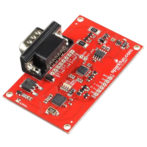
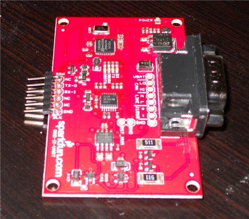
Before we get our hands dirty with commands, let’s understand the hardware. The OBD-II UART board is designed to bridge the gap between your car’s OBD-II system and your computer or microcontroller. It’s equipped with key components:
- STN1110 OBD to UART Interpreter: This is the brain of the operation. The STN1110 chip translates between the various OBD-II protocols used by different car manufacturers and the simple UART (Serial) interface you can use with your computer. It’s fully compatible with the popular ELM327 command set, ensuring broad compatibility and access to a wealth of anydata obd2 at commands pdf documentation online that often references ELM327.
- MCP2551 CAN Transceiver: While we’re focusing on UART communication here, the board also includes a CAN transceiver, opening doors for more advanced projects involving CAN bus communication in vehicles.
- Voltage Regulation: The board regulates voltage to both 5V and 3.3V, ensuring stable operation for all components.
Understanding car diagnostics is easier than you think with the right tools.
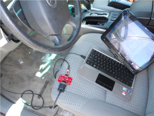
Connecting for the First Time: Serial Communication
Let’s get connected and send our first commands! We’ll start by establishing serial communication between the OBD-II UART board and your computer using an FTDI Basic breakout board.
Steps:
-
Solder Headers: Solder male headers to the 6-pin FTDI-compatible header on the OBD-II UART board. This allows for easy connection with jumper wires or an FTDI cable.
-
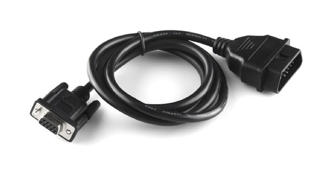
Connect to Your Vehicle’s OBD Port: Locate the OBD-II port in your car (usually under the dashboard on the driver’s side). Connect the OBD-II UART board to this port using an OBD-II to DB9 cable. Ensure a firm connection.
An OBD-II to DB9 cable is essential for connecting your OBD-II UART board to your car’s diagnostic port.
-
FTDI Connection: Connect the FTDI Basic to the soldered headers on the OBD-II UART board. Match the TX, RX, and GND pins. Then, connect the FTDI Basic to your computer via a mini-USB cable.
-
Serial Terminal Setup: Open your favorite serial terminal program (like PuTTY, Tera Term, or Arduino Serial Monitor). Configure the connection to:
- Baud Rate: 9600 bps
- Data bits: 8
- Stop bits: 1
- Parity: None
Setting up your serial connection is the first step to communicating with your car’s computer.
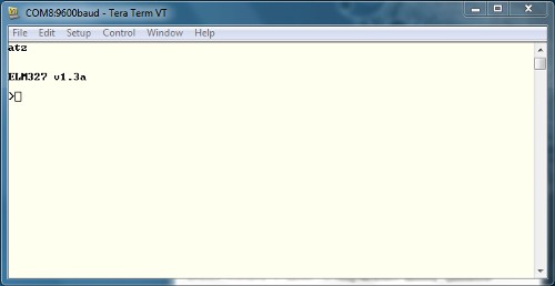
- Send Your First AT Command: In the serial terminal, type
ATZand press Enter. This is the reset command. You should see LEDs flash on the OBD-II UART board, and a startup message appear in the terminal. This confirms successful communication!
A successful startup prompt indicates your OBD-II UART is ready to receive commands.
If you see garbled characters, double-check your serial port settings – baud rate, data bits, stop bits, and parity are crucial.
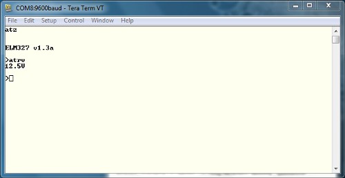
- Check Voltage: Try another AT command:
ATRVand Enter. This reads the system voltage. The response should be close to your car battery’s voltage.
Verifying the system voltage ensures the OBD-II UART is receiving power from your vehicle.
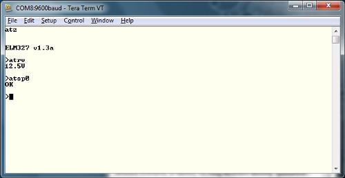
- Automatic Protocol Detection: Before querying vehicle parameters, we need to ensure the correct OBD-II protocol is selected. With your car’s ignition in the “On” position (engine not necessarily running), send the command
ATSP0and Enter. The board will auto-detect the protocol and respond with “OK”.
Automatic protocol detection simplifies setup and ensures compatibility with your vehicle.
Delving into OBD Commands and PIDs
Now that we have communication established, let’s explore the core of OBD-II interaction: OBD commands. These commands are hexadecimal codes sent as ASCII characters. They consist of a mode and a Parameter ID (PID).
OBD Modes: There are 10 standard OBD modes, each serving a different purpose:
| Mode Number | Mode Description |
|---|---|
| 01 | Current Data |
| 02 | Freeze Frame Data |
| 03 | Diagnostic Trouble Codes (DTCs) |
| 04 | Clear Trouble Codes |
| 05 | Test Results/Oxygen Sensors |
| 06 | Test Results/Non-Continuous Testing |
| 07 | Show Pending Trouble Codes |
| 08 | Special Control Mode |
| 09 | Request Vehicle Information |
| 0A | Request Permanent Trouble Codes |
For a deeper dive into OBD PIDs, Wikipedia and dedicated automotive diagnostic resources are excellent starting points. Crucially, for a complete list of supported commands and their detailed explanation, searching for anydata obd2 at commands pdf will lead you to valuable resources, often including ELM327 datasheets and command lists which are highly relevant to the STN1110 chip used on the OBD-II UART board. These PDF documents are your best friend for understanding the nitty-gritty details of each command.
Example OBD Command: Requesting Supported PIDs:
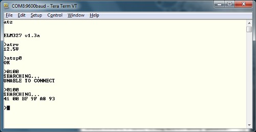
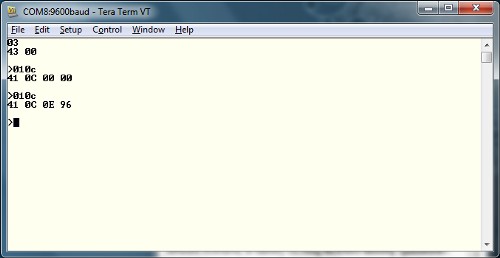
One of the most useful initial commands is 0100. This command, sent as ASCII characters, translates to: “In Mode 01 (Current Data), what PIDs are supported?”. Type 0100 in your serial terminal and press Enter.
The response will start with 41 (0x40 + 0x01, indicating Mode 01 response) and 00 (the PID requested). The subsequent bytes (e.g., BF 9F A8 93) are a bitmask indicating which PIDs are supported by your vehicle in Mode 01. Consult anydata obd2 at commands pdf resources or ELM327 documentation to interpret these bitmasks and understand which parameters your car makes available.
Example OBD Command: Reading Engine RPM:
To read your engine’s RPM, use the command 010C. Send this to your OBD-II UART board.
The response again starts with 41 and 0C. The data bytes following (e.g., 0E 96) represent the RPM in hexadecimal. Convert this hexadecimal value to decimal (e.g., 0E96 hex = 3734 decimal). Engine RPM is often given in quarters of RPM, so divide by 4 (3734 / 4 = 933.5 RPM).
Remember to always refer to reliable documentation, such as anydata obd2 at commands pdf files or the ELM327 datasheet, to understand the units and scaling factors for different PIDs.
Integrating with Arduino for Standalone Projects
While computer connection is great for initial exploration, the real power of OBD-II UART comes when you embed it in projects. Let’s connect it to an Arduino and display real-time data on an LCD.
Materials:
- Arduino Uno (or compatible 5V Arduino)
- Jumper wires
- Serial LCD
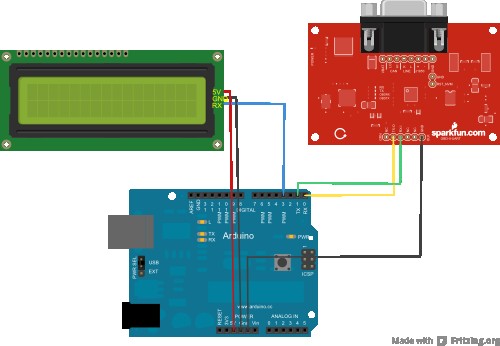
Wiring:
Follow this connection diagram and table:
| Arduino Pin | Serial LCD Pin | OBD-II-UART Pin |
|---|---|---|
| GND | GND | GND |
| 5V | 5V | None |
| D3 | Rx | None |
| D0 (Rx) | None | Tx-O |
| D1 (Tx) | None | Rx-I |
Arduino Code (Sketch):
You can download the example Arduino sketch here or find the latest version on GitHub.
Key points about the Arduino sketch:
- SoftwareSerial Library: Uses the SoftwareSerial library to communicate with the LCD, freeing up the hardware serial port for OBD-II UART communication.
- Data Display: The sketch reads vehicle speed and RPM and displays them on the serial LCD.
- OBD Command Sending: It sends the
010Dcommand for speed and010Cfor RPM. - Response Handling: The
getResponse()function handles serial data reception from the OBD-II UART board.
Important Note: Disconnect the OBD-II UART RX line from Arduino TX (pin 1) before uploading code to the Arduino to prevent communication conflicts and potential issues. Also, the Arduino in this setup is typically powered separately via USB or a battery, not by the OBD-II board.
Soldering headers makes connecting the OBD-II UART board to other components like Arduino easier.
Expanding Your OBD-II Horizons
This guide provides a strong foundation. To go further:
- Explore More PIDs: Use the
0100command to discover supported PIDs on your vehicle and experiment with reading other parameters like coolant temperature, throttle position, and more. Your anydata obd2 at commands pdf resources and ELM327 documentation will be essential here. - DTC Reading and Clearing: Learn to use Mode 03 to read diagnostic trouble codes (check engine light codes) and Mode 04 to clear them (use with caution and understanding!).
- Advanced Projects: Imagine building a custom dashboard display, a data logger for track days, or even a smart system that alerts you to potential vehicle issues before they become major problems.
Software Resources:
Explore free OBD-II software available online. Many programs can visualize OBD-II data in graphs and gauges, often requiring just a serial port connection. Check the GitHub repository for links to useful software tools.
Further Learning:
- CAN Bus: If you’re intrigued by vehicle networking, delve into CAN bus communication. The OBD-II UART board supports CAN, opening up a whole new realm of automotive hacking and data access.
- OBD-II Standards Documents: For the most authoritative information, consider exploring official OBD-II standards documents (though these can be quite technical).
By mastering OBD-II AT commands and leveraging resources like anydata obd2 at commands pdf documents, you unlock a powerful ability to understand your vehicle’s inner workings, diagnose issues, and even create exciting custom automotive projects. Start exploring, experiment safely, and enjoy the journey of automotive discovery!
Resources and Further Reading:
- ELM327 Datasheet: A fundamental document for understanding the command set. Search for “ELM327 datasheet PDF”.
- STN1110 Resources: ScanTool, the manufacturer of the STN1110 chip, offers resources on their website.
- Wikipedia: OBD-II PIDs: https://en.wikipedia.org/wiki/OBD-II_PIDs
- SparkFun Getting Started with OBD-II Tutorial: https://learn.sparkfun.com/tutorials/getting-started-with-obd-ii
Explore these resources, dive into the world of anydata obd2 at commands pdf documentation, and transform your understanding of automotive technology!