Understanding the On-Board Diagnostics II (OBD2) port in your 2005 Chevy Colorado is crucial for effective vehicle maintenance and diagnostics. This port serves as the gateway to your truck’s computer systems, allowing mechanics and DIY enthusiasts to read trouble codes, monitor live data, and ensure optimal performance. A key question for anyone working with their OBD2 port is understanding its wiring and pin configuration. This article will delve into the 2005 Chevy Colorado OBD2 port pinout, explaining where the wires connect and what each pin is responsible for.
Decoding the OBD2 Port Connections in Your 2005 Chevy Colorado
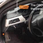
The OBD2 port in your 2005 Chevy Colorado isn’t just a simple connector; it’s a sophisticated interface linked to various modules within your vehicle. Specifically, the Engine Control Module (ECM) and Body Control Module (BCM) are key components that communicate through the OBD2 port.
-
ECM & TCM Communication: The ECM (Engine Control Module) and, if applicable, the TCM (Transmission Control Module) communicate directly with the OBD connector via specific pins. In the 2005 Chevy Colorado, these modules primarily utilize pins 6 and 14 of the OBD2 port for communication. These pins are part of the Controller Area Network (CAN) bus, enabling high-speed data exchange for crucial engine and transmission diagnostics.
-
BCM Communication: The Body Control Module (BCM), which manages various body electronics and comfort features, also interfaces with the OBD2 port. In the 2005 Chevy Colorado, the BCM typically communicates through pin 2 of the OBD2 connector, utilizing Class 2 serial data. This allows for diagnostics and communication related to body systems.
To visualize these connections and understand the full pinout, wiring diagrams are invaluable.
2005 Chevy Colorado OBD2 Port Pinout Diagram and Pin Functions
While we cannot directly display interactive diagrams here, understanding the standard OBD2 pinout is essential. The OBD2 port is a 16-pin connector, and each pin is assigned a specific function according to industry standards and manufacturer-specific implementations.
Here’s a breakdown of key pins relevant to the 2005 Chevy Colorado, based on the information discussed:
-
Pin 2: J1850 Bus Positive (Class 2 Serial Data for BCM) – This pin is dedicated to Class 2 serial data communication, primarily used by the BCM in GM vehicles like the Chevy Colorado for body system diagnostics.
-
Pin 4: Chassis Ground – Provides a ground connection for the diagnostic tool and the vehicle’s electrical system.
-
Pin 5: Signal Ground – Another ground reference, ensuring signal integrity for data communication.
-
Pin 6: CAN High (ECM & TCM Communication) – Part of the CAN bus high signal, crucial for ECM and TCM communication in many modern vehicles, including the 2005 Chevy Colorado.
-
Pin 7: K-Line ISO 9141-2 & ISO/DIS 14230-4 – Used for ISO 9141-2 and ISO 14230-4 communication protocols, which might be relevant for certain diagnostic functions, although CAN is more prevalent in systems connected to pins 6 and 14.
-
Pin 10: J1850 Bus Negative – The negative side of the J1850 communication bus, complementing pin 2.
-
Pin 14: CAN Low (ECM & TCM Communication) – The CAN bus low signal, working in conjunction with pin 6 for robust data transmission between the ECM/TCM and diagnostic tools.
-
Pin 16: Battery Power – Provides battery voltage to the diagnostic tool, typically 12V.
An example image of a standard OBD2 port connector highlighting pin numbers, useful for visually locating specific pins mentioned in the article concerning the 2005 Chevy Colorado OBD2 system.
While a generic OBD2 pinout provides a starting point, always refer to the specific wiring diagrams for the 2005 Chevy Colorado for precise details, especially when troubleshooting or performing electrical repairs. These diagrams will offer connector views and wire colors, making tracing circuits much easier.
The Importance of the Data Link Resistor in the OBD2 System
In GM vehicles utilizing CAN communication, like the 2005 Chevy Colorado, a Data Link Resistor plays a vital role in ensuring proper network function. This resistor, typically 120 ohms, acts as a terminating resistor for the GM LAN communication bus. It’s designed to be wired into the system to complete the circuit and prevent signal reflection, which can disrupt communication.
Often, one terminating resistor is integrated within the ECM or TCM, and another external Data Link Resistor is placed elsewhere in the network. When these two 120-ohm resistors are in parallel, the total resistance between pins 6 and 14 of the OBD2 connector should measure approximately 60 ohms.
A visual representation of a Data Link Resistor, a component essential for proper communication within the 2005 Chevy Colorado’s OBD2 system and GM LAN, often located near the OBD2 connector or within vehicle modules.
Checking the resistance between pins 6 and 14 with a multimeter can be a useful diagnostic step. If you measure around 60 ohms with everything connected, it indicates the terminating resistors are likely in place and functioning correctly. If the resistance is significantly different, it could point to a missing or faulty Data Link Resistor, or other issues within the CAN bus network.
Conclusion
Understanding the 2005 Chevy Colorado OBD2 port pinout, particularly the connections to the ECM, BCM, and the role of the Data Link Resistor, is essential for anyone diagnosing or repairing this vehicle’s electronic systems. By knowing which pins are responsible for which communication protocols, and by utilizing wiring diagrams for detailed circuit tracing, you can effectively troubleshoot issues and maintain your 2005 Chevy Colorado’s optimal performance. Always consult the official service manual for the most accurate and detailed wiring information specific to your vehicle.