For Honda enthusiasts and mechanics diving into engine swaps or performance tuning, understanding the electrical system is crucial. When it comes to the ’96 OBD2 Honda Civic with a VTEC engine, the pinout of your Electronic Control Unit (ECU) is your roadmap. This guide is dedicated to unraveling the complexities of the 96 Obd2 Civic Vtec Pinout, providing you with a comprehensive resource to ensure your wiring is spot-on, whether you’re swapping engines, upgrading your VTEC system, or simply troubleshooting electrical issues.
Decoding OBD2 and VTEC in Your 1996 Civic
Before we delve into the specifics of the pinout, let’s set the stage by understanding the key technologies at play in your 1996 Honda Civic. 1996 marked a significant year for automotive electronics as it was the year On-Board Diagnostics II (OBD2) became standard in the United States. This system is more advanced than its predecessor, OBD1, offering enhanced diagnostics and emissions monitoring. For your ’96 Civic, this means a more sophisticated ECU and diagnostic capabilities.
Coupled with OBD2, the Variable Valve Timing and Lift Electronic Control (VTEC) system is Honda’s renowned technology for optimizing engine performance and fuel efficiency. VTEC engines, like the D16Y8 in many ’96 Civics, deliver a blend of low-end torque and high-end horsepower by altering valve lift and duration at different engine speeds. Proper wiring is absolutely essential for the VTEC system to function correctly. Incorrect connections can lead to performance issues, engine damage, or even failure to engage VTEC.
Unpacking the 96 OBD2 Civic VTEC ECU Pinout
Now, let’s get to the heart of the matter: the ECU pinout. For a 1996 OBD2 Honda Civic with a VTEC engine, you’re likely dealing with an OBD2A ECU. While specific ECU codes can vary, understanding the general pinout for VTEC functionality is key.
While a direct pinout diagram specifically labeled “96 obd2 civic vtec pinout” might be elusive as a single image, we can derive the necessary information by referencing general OBD2A Honda pinouts and focusing on the VTEC-related pins. Figures 6 and 7 from the original article provide valuable insights into OBD2A and OBD2B hybrid pinouts, which are highly relevant.
Key VTEC Related Pins (General OBD2A – Refer to Figures 6 & 7 for Visuals):
It’s important to consult a full OBD2A ECU pinout diagram for your specific ECU code for comprehensive wiring tasks. However, for VTEC functionality, focus on these critical connections:
- VTEC Solenoid Control: This pin sends the signal from the ECU to activate the VTEC solenoid. The solenoid, when energized, allows oil pressure to engage the VTEC mechanism in the engine’s valvetrain. Incorrect wiring here will prevent VTEC from engaging.
- VTEC Pressure Switch: This pin provides feedback to the ECU, confirming that oil pressure is sufficient for VTEC engagement. This is a safety measure; if oil pressure is too low, the ECU will not engage VTEC, preventing potential engine damage.
- Knock Sensor (Potentially): While not directly VTEC related, the knock sensor is often wired in proximity to VTEC circuits in engine harnesses. The knock sensor detects engine knocking or detonation, allowing the ECU to adjust timing and prevent engine damage. Figure 6 shows the knock sensor pin in OBD2A pinouts.
It’s critical to remember that pin locations and wire colors can sometimes vary slightly depending on the exact model and sub-model of your 1996 Civic. Always double-check with a wiring diagram specific to your vehicle if possible.
Figure 1: While this diagram is for OBD1 ECUs, it illustrates the general principles of wiring VTEC solenoid and pressure switch, which are conceptually similar in OBD2 systems. Note the VTEC solenoid and VTEC pressure switch connections in this OBD1 example as a starting point for understanding.
Wiring Diagrams and Practical VTEC Applications
While a pinout description is essential, visual wiring diagrams are invaluable for practical application. Unfortunately, the original article does not contain a dedicated “96 obd2 civic vtec pinout” diagram. However, by combining the pinout information with general Honda wiring principles and the diagrams provided (Figures 1, 6, and 7), we can create a mental wiring map.
Simplified VTEC Wiring Scenario for a ’96 OBD2 Civic:
- VTEC Solenoid Wire: Locate the VTEC solenoid on your engine’s cylinder head. Identify the wire coming from the solenoid. This wire needs to connect to the VTEC solenoid control pin on your OBD2A ECU (refer to Figure 6 for general location – confirm with your specific pinout).
- VTEC Pressure Switch Wires: The VTEC pressure switch usually has two wires. One wire is typically a ground, and the other is the signal wire that goes to the ECU. Identify the signal wire and connect it to the VTEC pressure switch pin on your OBD2A ECU (again, Figure 6 is a starting point). The ground wire should be grounded to the chassis or engine block.
- Power Source: The VTEC solenoid and pressure switch circuits require a 12V power source. This is usually supplied through the main relay and ignition system. Ensure your VTEC circuit is properly fused and powered.
Engine Swaps and 96 Civic VTEC Wiring:
If you are performing an engine swap in a 1996 Civic and retaining the OBD2 system, you will likely need to adapt the engine harness to your chassis harness. Understanding the ’96 OBD2 Civic VTEC pinout becomes critical in these situations:
- OBD2 Engine into 96 OBD2 Civic: If swapping in another OBD2 VTEC engine (e.g., B16A2, B18C1), the VTEC wiring should be relatively straightforward as both engine and chassis are OBD2. However, verify pin compatibility and wire continuity.
- OBD1 Engine into 96 OBD2 Civic (Using OBD1 ECU): This scenario requires more significant wiring changes. You will need to bypass or adapt the OBD2 wiring for VTEC to work with an OBD1 ECU. Figure 1 becomes more relevant here, but you’ll need to cross-reference OBD1 and OBD2 pinouts carefully. Adapters and conversion harnesses can simplify this process.
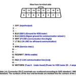
Figure 6: This OBD2A hybrid pinout diagram is crucial for understanding the general location of VTEC-related pins and other engine control circuits in a ’96-98 Honda Civic. Use this as a visual guide when tracing wires and making connections.
Troubleshooting VTEC Wiring Issues Using the Pinout
The 96 OBD2 Civic VTEC pinout is not just for swaps; it’s also essential for troubleshooting. If your VTEC is not engaging, or you suspect wiring problems, the pinout can guide your diagnostic process:
- Continuity Checks: Use a multimeter to check the continuity of the wires between the VTEC solenoid, pressure switch, and the corresponding pins on the ECU connector. Broken or damaged wires are common culprits.
- Voltage Checks: Verify that the VTEC solenoid and pressure switch are receiving the correct voltage (12V when VTEC should be active). Check for voltage at the ECU pin and at the components themselves.
- Ground Checks: Ensure proper ground connections for the VTEC pressure switch and other related sensors. Poor grounds can cause intermittent issues.
- ECU Pin Inspection: Carefully inspect the ECU connector pins for corrosion, damage, or bent pins. A faulty ECU pin can disrupt the VTEC signal.
Optimizing VTEC Wiring for Performance and Reliability
Beyond just getting VTEC to work, optimizing your wiring can improve performance and reliability:
- Quality Wiring: Use high-quality automotive-grade wire that is appropriately sized for the VTEC circuit. Avoid thin or brittle wires that can break or cause voltage drops.
- Secure Connections: Ensure all wire connections are secure and properly insulated. Soldering and using heat shrink tubing is recommended for durable and weather-resistant connections.
- Wire Routing: Route wires neatly and away from heat sources, sharp edges, and moving parts. Proper wire routing prevents damage and shorts.
- Minimize Resistance: Keep wire runs as short as practical to minimize resistance in the VTEC circuit. Excessive resistance can weaken the VTEC signal.
Conclusion
Understanding the ’96 OBD2 Civic VTEC pinout is fundamental for anyone working on the electrical system of these vehicles. Whether you are undertaking an engine swap, enhancing performance, or diagnosing issues, this guide, combined with relevant wiring diagrams and careful methodology, will empower you to confidently tackle your wiring tasks. Always prioritize safety, double-check your connections, and consult professional resources when needed to ensure a successful and reliable outcome for your Honda Civic VTEC project.