The 4th generation F-body, encompassing the Chevrolet Camaro and Pontiac Firebird from 1993-2002, is a favorite among enthusiasts for its performance and modifiability. Understanding the electrical system, particularly the wiring related to the OBD2 gauge cluster, is crucial for diagnostics, repairs, and modifications. This article delves into the under-dash connectors of these vehicles, providing detailed pinout information essential for working on your 4th gen F-body’s electrical system.
Located beneath the dashboard, these connectors serve as central hubs for various electrical signals, including those vital for your instrument cluster and the OBD2 diagnostic system. Navigating these connections can seem daunting, but with clear information, you can confidently troubleshoot issues or undertake electrical projects.
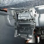
Here’s a breakdown of the pinouts for the key under-dash connectors in 4th gen F-body vehicles, specifically relevant to systems interacting with the OBD2 and gauge cluster:
6-Wire Connector Pinout
This connector manages critical power feeds for ignition and various accessories. While not directly linked to OBD2 data, it powers circuits essential for the gauge cluster and overall vehicle operation, impacting the systems monitored by OBD2.
- Cavity A (Red): Ignition Switch and Related Fuses – Powers the ignition switch and feeds multiple fuses (27, 28, 29, 30, 33, 34, 35) crucial for various vehicle systems.
- Cavity B (Red): AC Blower and Circuit Breakers – Supplies power to the AC blower relay and circuit breakers (1, 3, 4), which are indirectly related to vehicle sensor readings that OBD2 monitors.
- Cavity C (Red): Headlight Switch and Fuse – Powers the headlight switch and fuse 31, part of the vehicle’s electrical system monitored for faults.
- Cavity D: Unknown Function
- Cavity E (Yellow): Starter Solenoid to Theft Deterrent Relay – Connects the starter solenoid to the theft deterrent relay, an engine starting circuit indirectly related to OBD2 monitoring.
- Cavity F: Unknown Function
10-Wire Connector Pinout
This connector is more directly related to the gauge cluster and OBD2 system, carrying signals for gauges, warning lights, and diagnostic information.
- Cavity A (Tan): Oil Pressure Gauge – Directly feeds the oil pressure gauge signal to the instrument cluster.
- Cavity B (Dk Grn/Wh): AC Control Request – Signal to the AC control module requesting air conditioning, a system monitored by vehicle sensors.
- Cavity C (Brown): Alternator to “Check Gauges” Light – Connects the alternator to the “check gauges” light, alerting to potential charging system issues, which can be further diagnosed via OBD2.
- Cavity D (Pink): Change Oil Light – Signal for the change oil light in the gauge cluster.
- Cavity E (Blk/Wh): Low Windshield Fluid Light – Signal for the low windshield fluid light in the cluster.
- Cavity F (Brn/Wh): Low Oil Level Light – Signal for the low oil level light in the gauge cluster.
- Cavity G (White): ABS Light – Signal for the Anti-lock Braking System (ABS) light, a critical safety system often diagnosed through OBD2.
- Cavity H: Unknown Function
- Cavity J (Yel/Blk): Low Coolant Light – Signal for the low coolant light in the instrument cluster.
- Cavity K (Dk Grn): Ignition Switch, Temp Gauge – Connects to the ignition switch for bulb testing and feeds the temperature gauge signal to the cluster.
37-Wire Connector Pinout
The 37-wire connector is a major hub, carrying a wide array of signals, including vehicle speed, brake signals, data link connector (DLC) connections for OBD2, and various control module signals.
- Cavity A1 (White): Brake Light Switch to EBCM – Signal from the brake light switch to the Electronic Brake Control Module (EBCM), crucial for ABS and traction control systems, which are OBD2 diagnosable.
- Cavity A2: Not Used
- Cavity A3 (Dk Grn): Power Antenna Relay
- Cavity A4 (Bare): Drain Return for Rear Wheel Speed Sensor – Ground for rear wheel speed sensor wiring, vital for ABS and vehicle stability systems, and indirectly for OBD2 data accuracy.
- Cavity A5 (White): To Red 5 Cavity Connector
- Cavity A6: Not Used
- Cavity B1 (Dk Blu): Theft Deterrent Module “Fuel Enable Signal” – Signal to enable fuel delivery, part of the theft deterrent system.
- Cavity B2 (Ppl): Cruise Control “Release Switch”
- Cavity B3 (Yel): Police Front Flashing Lamps (Police Package Specific)
- Cavity B4 (Dk Grn/Wh): Vehicle Speed Signal from PCM – Vehicle speed signal from the Powertrain Control Module (PCM), essential for the speedometer in the gauge cluster and vehicle speed-related OBD2 parameters.
- Cavity B5 (White): To Red 5 Cavity Connector
- Cavity B6 (Tan): Data Link Connector (DLC) Pin 9 – Connection to pin 9 of the OBD2 Data Link Connector, used for diagnostic communication.
- Cavity C1 (Pink): Ignition Switch and Related Fuses – Powers ignition circuits and fuses (11, 12, 13, 14, 15).
- Cavity C2 (Gray): Fuel Pump Feed – Power feed to the fuel pump, critical for engine operation and monitored by the PCM and OBD2 system.
- Cavity C3 (Ppl): Wiper Switch “HI”
- Cavity C4 (Gray): Wiper Switch “Wash”
- Cavity D1: Not Used (Buick Only)
- Cavity D2: Not Used (Buick Only)
- Cavity E1 (Yel): Left Front Wheel Speed Sensor – Input from the left front wheel speed sensor, essential for ABS and traction control.
- Cavity F1 (Bare): Same as E1 above (Ground for Wheel Speed Sensor)
- Cavity F2 (Lt Blu): Same as E1 above (Wheel Speed Sensor Signal)
- Cavity G1 (Orn): Ignition “Run” and Related Fuses – Powers circuits when the ignition is in the “Run” position and feeds fuses (16, 17, 18, 20).
- Cavity G2 (Pink): Wiper Switch “Mist/Off”
- Cavity G3 (Dk Grn): Wiper Switch “Off/Mist/Low/Hi”
- Cavity G4 (Gray): Power Antenna Relay “UP”
- Cavity H1 (White): Tachometer Signal (Impala Only) – Tachometer signal for the instrument cluster, relevant for engine RPM display.
- Cavity H2 (White): Power Antenna Relay “Down”
- Cavity H3 (Lt Blu): Police Front Flashing Lamps (Police Package Specific)
- Cavity H4 (Dk Grn): Police Front Flashing Lamps (Police Package Specific)
- Cavity H5 (Orn/Blk): Trunk Release and Brake/Trans Interlock – Powers the trunk release relay and brake/transmission interlock solenoid, safety and convenience features.
- Cavity H6 (Wh/Blk): Ground for Theft Deterrent, Cruise, Park/Neutral Switch – Common ground point for several modules and switches.
- Cavity J1-J5: Not Used
- Cavity J6 (Ppl): Data Link Connector (DLC) Pin 2 – Connection to pin 2 of the OBD2 Data Link Connector, another key pin for diagnostic communication.
Understanding these connector pinouts is fundamental when diagnosing electrical issues related to your 4th gen F-body’s gauge cluster or OBD2 system. Always refer to a vehicle-specific wiring diagram for your exact model year for the most accurate information, and exercise caution when working with automotive electrical systems.