Maintaining your 2017 Chevy City Express Van means understanding its vital components, including the OBD2 port and fuse boxes. These are essential for diagnostics and electrical system maintenance. Knowing the location of the OBD2 port allows you to connect diagnostic tools to read trouble codes and assess your van’s health. Similarly, understanding your fuse box locations and diagrams is crucial for troubleshooting and resolving electrical issues. This guide will show you where to find both the OBD2 port and the fuse boxes in your 2017 Chevy City Express Van, providing you with the necessary information for effective vehicle maintenance.
Finding the OBD2 Port in Your 2017 Chevy City Express Van
The On-Board Diagnostics II (OBD2) port is a standardized interface used to access your vehicle’s computer system for diagnostics and monitoring. For the 2017 Chevy City Express Van, the OBD2 port is typically located within the driver’s side interior, making it easily accessible for technicians and vehicle owners alike.
While the exact placement can slightly vary, you can generally find the OBD2 port for your 2017 Chevy City Express Van under the dashboard on the driver’s side. Look for it in the area beneath the steering wheel column. It’s usually not hidden behind a panel, allowing for straightforward access when you need to plug in a diagnostic scanner.
Once located, you can use an OBD2 scanner to read diagnostic trouble codes (DTCs), check engine light warnings, and access real-time vehicle data. This is an invaluable tool for both preventative maintenance and troubleshooting potential problems with your Chevy City Express Van.
2017 Chevy City Express Van Fuse Box Locations and Diagrams
Your 2017 Chevrolet City Express Van is equipped with two fuse box locations, each serving different circuits throughout the vehicle. Understanding the function of each fuse and relay is essential for diagnosing and resolving electrical issues. Below are the locations and diagrams for both fuse boxes in your van.
Engine Compartment Fuse Block Diagram
The primary fuse box is located in the engine compartment. This fuse block houses fuses and relays that protect critical engine and vehicle control systems.
| Type | No. | Description |
|---|---|---|
| Fuse FMX/JCase 50A | 1 | ABS motor |
| Fuse FMX/JCase 40A | 2 | ABS module |
| Fuse MINI | 3 | Right trailer stoplamp/Turnlamp |
| Fuse MINI 10A | 6 | Fuel system control module/Ignition |
| Fuse MINI 10A | 7 | Body control module 5 |
| Fuse MINI 10A | 8 | Body control module 7 |
| Fuse MINI 10A | 9 | Body control module 4 |
| Fuse MINI 10A | 10 | Instrument cluster |
| Fuse MINI | 11 | Trailer wiring |
| Fuse MINI | 12 | Interior rear vision camera module |
| Fuse MINI 10A | 13 | Not used |
| Fuse MINI 15A | 14 | Windshield washer |
| Fuse MINI 20A | 16 | Horn |
| Fuse MINI 15A | 17 | Transmission |
| Fuse MINI 15A | 18 | A/C |
| Fuse MINI 10A | 19 | Engine control module battery |
| Fuse MINI | 21 | Left trailer stoplamp/Turnlamp |
| Fuse MINI 30A | 24 | Fuel pump |
| Fuse MINI 20A | 25 | Auxiliary power outlet |
| Fuse MINI 10A | 26 | Body control module 3 |
| Fuse MINI 10A | 27 | Special equipment option |
| Fuse MINI 10A | 28 | Airbag |
| Fuse MINI 10A | 29 | Steering wheel sensor |
| Fuse MINI 15A | 30 | Engine control module/Ignition/ Glow plug module |
| Fuse MINI 15A | 31 | Transmission control module/ Ignition |
| Fuse MINI 10A | 32 | Transmission control module battery |
| Fuse MINI | 33 | Rear parking aid module |
| Fuse MINI | 35 | Fuel operated heater module |
| Fuse MINI 20A | 36 | Fuel system control module battery |
| Fuse FMX/JCase | 42 | Trailer wiring |
| Fuse FMX/JCase | 43 | EV fan clutch |
| Fuse FMX/JCase 40A | 44 | Starter solenoid |
| Fuse FMX/JCase | 45 | Engine control module/Powertrain |
| Fuse FMX/JCase | 47 | Cooling fan – low |
| Fuse MINI 10A | 51 | Left high-beam headlamp |
| Fuse MINI 10A | 52 | Right high-beam headlamp |
| Fuse MINI 10A | 53 | Left low-beam headlamp |
| Fuse MINI 10A | 54 | Right low-beam headlamp |
| Fuse MINI 25A | 55 | Wipers |
| Fuse MINI 10A | 56 | Canister vent solenoid |
| Fuse MINI 10A | 58 | Body control module 2 |
| Fuse MINI 10A | 59 | Body control module 1 |
| Fuse MINI 10A | 62 | O2 sensor 2/EV [diesel] |
| Fuse MINI 15A | 64 | Mass air flow/ Canister vent |
| Fuse MINI 20A | 65 | Ignition/Injectors – odd |
| Fuse MINI 10A | 66 | Daytime running lamps 2 (LOLVL-V22) (if equipped) |
| Fuse MINI 15A | 67 | Daytime running lamps 1 (UPLVL +V22) (if equipped) |
| Fuse MINI 15A | 68 | Auxiliary stoplamps |
| Fuse MINI | 69 | Trailer stoplamps – |
| Fuse MINI | 71 | Fuel heater/Flex fuel sensor |
| Fuse MINI 10A | 72 | Body control module 6 |
| Fuse MINI 20A | 73 | Lighter/Data link connector |
| Fuse FMX/JCase 40A | 74 | Front blower |
| Fuse MINI 15A | 75 | Fuel injectors |
| Fuse MINI 10A | 77 | O2 sensor 2 |
| Fuse MINI 10A | 78 | Engine control module/Powertrain |
| Fuse MINI 20A | 79 | Ignition/Injectors – even |
| Relay | 15 | Run/Crank |
| Relay | 38 | Fuel pump |
| Relay | 39 | Crank |
| Relay | 40 | A/C |
| Relay | 48 | EV fan clutch |
| Relay | 49 | Powertrain |
| Relay | 57 | Cooling fan – low |
| Relay | 60 | Fan control |
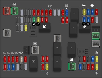
This diagram illustrates the layout and function of each fuse and relay within the engine compartment fuse block. Refer to your owner’s manual for the most accurate and up-to-date information, as specifications can sometimes vary.
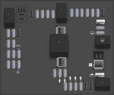
Floor Console Fuse Block Diagram
The second fuse box is located inside the cabin, specifically in the floor console area. This fuse box generally manages circuits related to interior functions and accessories.
| Type | No. | Description |
|---|---|---|
| Fuse MINI | F2 | Steering wheel sensor |
| Fuse MINI | F3 | Auxiliary parking lamps (cut-away) |
| Fuse MINI | F4 | Front parking lamps |
| Fuse MINI | F5 | Trailer parking lamps |
| Fuse MINI | F6 | Upfitter/Parking lamps |
| Fuse MINI | F7 | Right rear parking lamp |
| Fuse MINI | F8 | Left rear parking lamp |
| Fuse MINI | F9 | Exterior rearview mirror switch |
| Fuse MINI | F10 | Airbag/Automatic occupant sensing |
| Fuse MINI | F11 | OnStar (if equipped) |
| Fuse MINI | F13 | HVAC 2 |
| Fuse MINI | F14 | HVAC 1 |
| Fuse FMX/JCase | F16 | Upfitter 1 (if equipped) |
| Fuse MINI | F17 | Exterior rearview heated mirrors |
| Fuse MINI | F18 | Rear window defogger |
| Fuse MINI | F19 | Compass |
| Fuse MINI | F20 | Radio/Chime/ SiriusXM satellite radio (if equipped) |
| Fuse MINI | F21 | Remote function actuator/Tire pressure monitor |
| Fuse MINI | F22 | Ignition switch/ Discrete logic ignition sensor [PK3] |
| Fuse MINI | F23 | Instrument cluster |
| Fuse MINI | F25 | HVAC |
| Fuse MINI | F26 | Auxiliary/Trailer reverse lamps |
| Fuse MINI | F27 | Reverse lamps |
| Fuse FMX/JCase | F28 | Upfitter 2/Reading lamps (if equipped) |
| Fuse FMX/JCase | F29 | Rear blower |
| Fuse MINI | F30 | Upfitter/Courtesy lamps |
| Fuse MINI | F31 | Front door lock |
| Fuse MINI | F32 | Rear door lock |
| Fuse MINI | F33 | Cargo door unlock |
| Fuse MINI | F34 | Passenger door unlock |
| Fuse MINI | F35 | Rear passenger door unlock |
| Fuse MINI | F36 | Driver door lock |
| Relay | K1 | Run |
| Relay | K3 | Parking lamps |
| Relay | K4 | Upfitter 2 |
| Relay | K5 | Rear defogger |
| Relay | K6 | Retained accessory power |
| Circuit breaker | CB1 | Power seats |
| Circuit breaker | CB2 | Power windows |
This floor console fuse box diagram provides a detailed view of the fuses and relays responsible for your 2017 Chevy City Express Van’s interior electrical functions. Always consult your vehicle’s manual for the most accurate fuse and relay assignments.
Conclusion
Understanding the location of the OBD2 port and fuse boxes in your 2017 Chevy City Express Van is a fundamental aspect of vehicle maintenance. Whether you are diagnosing engine issues with an OBD2 scanner or troubleshooting electrical problems by checking fuses, this knowledge empowers you to take better care of your vehicle. Always refer to your owner’s manual for the most precise information and diagrams related to your specific 2017 Chevy City Express Van model. Regular checks and a basic understanding of these systems can contribute significantly to the longevity and reliable operation of your van.