Maintaining your 2014 Ford Mustang V6 involves understanding its electrical system, and a key part of that is knowing the location of your fuse boxes and the function of each fuse. This guide will walk you through the fuse box locations in your 2014 Mustang, including details relevant to the V6 model and the OBD2 port. Knowing your fuse box layout is crucial for diagnosing electrical issues and performing basic maintenance.
Your 2014 Ford Mustang V6, like other models, utilizes two primary fuse boxes. These are strategically placed to protect different circuits throughout your vehicle. Let’s explore each location and their respective fuse diagrams.
Understanding Your 2014 Ford Mustang Fuse Boxes
There are two main fuse box locations in the 2014 Ford Mustang:
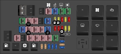
Engine Compartment Fuse Box
The engine compartment fuse box is typically the first place to check for issues related to engine components, power circuits, and critical vehicle systems.
This fuse box is located under the hood, usually on the driver’s side. Refer to the diagram below for fuse designations.
| Type | No. | Description |
|---|---|---|
| Fuse FLF/PAL 293 80A | 1 | Passenger compartment fuse panel |
| Fuse FMX/JCase 30A | 4 | Blower motor relay |
| Fuse FMX/JCase 20A | 5 | Power point (body) |
| Fuse FMX/JCase 40A | 6 | Rear defroster relay |
| Fuse FMX/JCase 40A | 7 | Cooling fan relay |
| Fuse FMX/JCase 40A | 8 | Anti-lock brake system pump |
| Fuse FMX/JCase 30A | 9 | Wipers |
| Fuse FMX/JCase 30A | 10 | Anti-lock brake system valve |
| Fuse FMX/JCase 20A | 12 | Differential fluid pump (Shelby only) |
| Fuse MINI 20A | 13 | Fuel pump relay (non-Shelby) |
| Fuse MINI 25A | 13 | Fuel pump relay (Shelby only) |
| Fuse MINI 20A | 14 | Fuel pump relay #2 (Shelby only) |
| Fuse MINI 10A | 15 | Intercooler pump relay (Shelby only) |
| Fuse MINI 20A | 16 | Heated seats |
| Fuse MINI 10A | 17 | Alternator sense |
| Fuse FMX/JCase 20A | 18 | Auxiliary body module |
| Fuse FMX/JCase 30A | 19 | Starter relay |
| Fuse FMX/JCase 30A | 20 | Rear amplifier (Shaker Pro radio) |
| Fuse FMX/JCase 30A | 21 | Powertrain relay |
| Fuse FMX/JCase 20A | 22 | Power point (instrument panel) |
| Fuse MINI 10A | 23 | Powertrain control module keep-alive power |
| Fuse MINI 10A | 24 | Brake on/off power |
| Fuse MINI 10A | 25 | A/C compressor relay |
| Fuse MINI 20A | 26 | Left high intensity discharge headlamp relay |
| Fuse MINI 20A | 27 | Right high intensity discharge headlamp relay |
| Fuse FMX/JCase 30A | 29 | Passenger front window |
| Fuse FMX/JCase 31A | 31 | Passenger power seat |
| Fuse FMX/JCase 30A | 32 | Driver power seat |
| Fuse FMX/JCase 30A | 33 | Front amplifier (Shaker radio) |
| Fuse FMX/JCase 30A | 34 | Driver front window motor |
| Fuse FMX/JCase 40A | 35 | Convertible top motor |
| Diode MINI | 36 | Fuel diode |
| Fuse MINI 15A | 38 | Fuel injectors (Shelby only) |
| Fuse MINI 5A | 39 | Heated mirrors |
| Fuse MINI 15A | 40 | Powertrain control module vehicle power 4 ignition coil |
| Relay | 41 | Fuel pump relay |
| Relay | 42 | Intercooler pump relay (Shelby only) |
| Relay | 43 | AC compressor relay |
| Relay | 44 | Fuel pump relay #2 (Shelby only) |
| Fuse MINI 5A | 45 | Powertrain control module run/start |
| Fuse MINI 5A | 46 | Powertrain control module vehicle power 3 general powertrain components |
| Fuse MINI 15A | 47 | Powertrain control module vehiele power 1 |
| Fuse MINI 15A | 48 | Powertrain control module vehicle power 5 |
| Fuse MINI 15A | 49 | Powertrain control module vehicle power 2 emissions related powertrain components |
| Relay | 50 | Cooling fan relay (high) |
| Relay | 51 | Blower motor relay |
| Relay | 52 | Starter relay |
| Relay | 53 | Rear defroster relay |
| Relay | 54 | Front wiper relay |
| Relay | 55 | Cooling fan relay (low) |
| Relay | 57 | Powertrain control module relay |
| Relay | 58 | Differential fluid pump (Shelby relay only) |
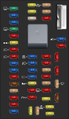
Passenger Compartment Fuse Box
The passenger compartment fuse box, sometimes referred to as the interior fuse box, handles circuits for interior functions, comfort features, and importantly, the OBD2 port.
This fuse box is typically located inside the car, often behind a panel in the dashboard or under the glove compartment. For the 2014 Ford Mustang V6, you’ll usually find it on the passenger side, often accessible once you open the passenger door and look at the side panel of the dashboard.
| Type | No. | Description |
|---|---|---|
| Fuse MINI 30A | 1 | Driver rear window (convertible only) |
| Fuse MINI 15A | 2 | Not used (spare) |
| Fuse MINI 15A | 3 | SYNC |
| Fuse MINI 30A | 4 | Passenger rear window (convertible only) |
| Fuse MINI 10A | 5 | Brake transmission shift interlock |
| Fuse MINI 20A | 6 | Turn signals, Hazard flashers |
| Fuse MINI 10A | 7 | Left low beam headlamp |
| Fuse MINI 10A | 8 | Right low beam headlamp |
| Fuse MINI 15A | 9 | Courtesy lamps |
| Fuse MINI 15A | 10 | Switch illumination, Pony projection lights |
| Fuse MINI 10A | 11 | Security module |
| Fuse MINI 7.5A | 12 | Power mirrors |
| Fuse MINI 5A | 13 | Not used (spare) |
| Fuse MINI 10A | 14 | Center information display Electronic finish panel, Global position system |
| Fuse MINI 10A | 15 | Climate control |
| Fuse MINI 15A | 16 | Not used (spare) |
| Fuse MINI 20A | 17 | Power door locks Trunk release |
| Fuse MINI 20A | 18 | Not used (spare) |
| Fuse MINI 25A | 19 | Not used (spare) |
| Fuse MINI 15A | 20 | Diagnostic connector |
| Fuse MINI 15A | 21 | Fog lamps |
| Fuse MINI 15A | 22 | Park lamps License lamps |
| Fuse MINI 15A | 23 | High beam headlamps |
| Fuse MINI 20A | 24 | Horn |
| Fuse MINI 10A | 25 | Demand lighting (battery saver), Visor vanity lamps |
| Fuse MINI 10A | 26 | Cluster (battery) |
| Fuse MINI 20A | 27 | Ignition switch feed |
| Fuse MINI 5A | 28 | Audio mute (start) |
| Fuse MINI 5A | 29 | Camera (run/start) |
| Fuse MINI 5A | 30 | Temperature sensor motor |
| Fuse MINI 10A | 31 | Restraints control module |
| Fuse MINI 10A | 32 | Reverse parking aid (non-Shelby), Vehicle dynamics control module (Shelby only) |
| Fuse MINI 10A | 33 | Not used (spare) |
| Fuse MINI 5A | 34 | Electronic stability control |
| Fuse MINI 10A | 35 | Auxiliary body module run/start |
| Fuse MINI 5A | 36 | Anti-theft system |
| Fuse MINI 10A | 37 | Rear defroster relay coil |
| Fuse MINI 20A | 38 | Not used (spare) |
| Fuse MINI 20A | 39 | Radio/Navigation |
| Fuse MINI 20A | 40 | Not used (spare) |
| Fuse MINI 15A | 41 | Accessory delay (windows, automatic dimming rear view mirror [including microphone and compass] and door switch III) |
| Fuse MINI 10A | 42 | Not used (spare) |
| Fuse MINI 10A | 43 | Heated seat relay coils |
| Fuse MINI 10A | 44 | Not used (spare) |
| Fuse MINI 5A | 45 | Wiper relay and module, Blower relay |
| Fuse MINI 7.5A | 46 | Passenger airbag deactivation indicator Occupant classification sensor |
| Circuit breaker MAXI | 47 | Circuit Breaker – Not used (spare) |
| Relay | 48 | Accessory delay relay (windows, automatic dimming rear view mirror (including microphone and compass and door switch III) |
OBD2 Port and Fuse Location Relevance
The OBD2 (On-Board Diagnostics II) port is essential for vehicle diagnostics and emission testing. It allows mechanics and car owners to connect scan tools to read diagnostic trouble codes (DTCs) and monitor vehicle parameters.
For the 2014 Ford Mustang V6, the OBD2 port is typically located beneath the dashboard on the driver’s side. While the OBD2 port itself doesn’t have a dedicated fuse in the sense of protecting just the port, it is powered through fuses within the passenger compartment fuse box.
Fuse #20 (15A) in the passenger compartment fuse box is designated for the “Diagnostic connector”. If you are experiencing issues with your OBD2 scanner not powering up or connecting, checking this fuse is a crucial first step. A blown fuse #20 could prevent the OBD2 port from functioning correctly.
By understanding the locations and diagrams of both fuse boxes, and specifically noting the fuse for the diagnostic connector, you are better equipped to maintain your 2014 Ford Mustang V6 and troubleshoot common electrical problems. Always consult your owner’s manual for the most accurate and detailed information specific to your vehicle.