Understanding your 2013 Toyota Corolla’s fuse box is crucial for diagnosing and resolving electrical issues. Fuses protect your vehicle’s electrical circuits from overloads, and knowing their locations and functions can save you time and money on repairs. This guide will provide you with a detailed look at the fuse box locations in your 2013 Toyota Corolla, with a specific focus on the OBD2 system and related fuses.
Your 2013 Toyota Corolla is equipped with two main fuse box locations: the engine compartment and under the driver’s side instrument panel. Each location houses fuses and relays that control different electrical systems throughout your vehicle.
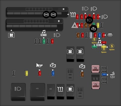
Engine Compartment Fuse Box Diagram
The primary fuse box is situated in the engine compartment. This box contains fuses and relays for critical systems such as the engine cooling fans, anti-lock braking system (ABS), heating and air conditioning, headlights, and various engine management components.
Here’s a detailed breakdown of the fuses and relays within the engine compartment fuse box:
| Type | No. | Description |
|---|---|---|
| Multi fuse block MUSB | 1 | (CDS FAN) Electric cooling fan(s) |
| Multi fuse block MUSB | 2 | (RDI FAN) Electric cooling fan(s) |
| Multi fuse block MUSB | 3 | (ABS NO. 3) Anti-lock brake system, vehicle stability control system |
| Multi fuse block MUSB | 4 | (ABS NO. 1) Anti-lock brake system, vehicle stability control system |
| Multi fuse block MUSB | 5 | (HTR) Air conditioning system |
| Multi fuse block MUSB | 6 | (ALT) Charging system, RDI FAN, ABS NO. 1, ABS NO. 3, HTR, HTR SUB NO. 1, HTR SUB NO. 3, ACC, CIG, ECU-IG NO. 2, HTR-IG, WIPER, WASHER, ECU-IG NO. 1, AM1, DOOR, STOP, FR DOOR, POWER, RR DOOR, RL DOOR, OBD, ACC-B, FR FOG, DEF, MIR HTR, TAIL, PANEL, PWR SEAT, SUNROOF |
| Multi fuse block MUSB | 7 | (EPS) Electric power steering |
| Multi fuse block MUSB | 8 | (GLOW) No circuit [If equipped] |
| Multi fuse block MUSB | 9 | (P/I) EFI MAIN HORN 1IG2 |
| Multi fuse block MUSB | 10 | (H-LP MAIN) H-LP LH LO, H-LP RH LO. H-LP LH HI, H-LP RH HI |
| Fuse MICRO2 10A | 11 | (EFI NO. 2) Emission control system |
| Fuse MICRO2 10A | 12 | (EFI NO. 1) Multiport fuel injection system/ sequentia multiport fuel injection system |
| Fuse MICRO2 10A | 13 | (H-LP RH HI) Right-hand headlight (high beam) |
| Fuse MICRO2 10A | 14 | (H-LP LH HI) Left-hand headlight (high beam) |
| Fuse MICRO2 10A | 15 | (H-LP RH LO) Right-hand headlight (low beam) |
| Fuse MICRO2 10A | 16 | (H-LP LH LO) Left-hand headlight (low beam) |
| Fuse MICRO2 10A | 17 | (ETCS) Electronic throttle control system |
| Fuse MICRO2 10A | 18 | (TURN-HAZ) Turn signa lights, emergency flashers |
| Fuse MICRO2 7.5A | 19 | (ALT-S) Charging system |
| Fuse MICRO2 7.5A | 20 | (AM2 NO. 2) Multiport fuel injection system/ sequentia multiport fuel injection system starting system |
| Fuse MICRO2 30A | 21 | (AM2) Starting system |
| Fuse MICRO2 20A | 22 | (STRG LOCK) Steering lock system |
| Fuse MICRO2 7.5A | 23 | (1G2 NO.2) Starting system |
| Fuse MICRO2 10A | 24 | (ECU-B2) Air conditioning system |
| Fuse MICRO2 10A | 25 | (ECU-B) Main body ECU gauge and meters, clock |
| Fuse MICRO2 15A | 26 | (RAD NO. 1) Audio system |
| Fuse MICRO2 10A | 27 | (DOME) Trunk light, smart key system, interior light |
| Fuse MICRO2 30A | 28 | (AMP) Audio system [If equipped] |
| Fuse MICRO2 10A | 29 | (MAYDAY) No circuit [If equipped] |
| Fuse MICRO2 10A | 30 | (SPARE) Spare fuse |
| Fuse MICRO2 30A | 31 | (SPARE) Spare fuse |
| Fuse MICRO2 20A | 32 | (SPARE) Spare fuse |
| Fuse MICRO2 20A | 33 | (EFI MAIN) Multiport fuel injection system/ sequential multiport fue injection system, EFI NO. 1. EFI NO. 2 |
| Fuse MICRO2 10A | 34 | (HORN) Horn |
| Fuse MICRO2 15A | 35 | (IG2) Multiport fuel injection system/ sequential multiport fuel injection system, starting system, IGN METER |
| Fuse MICRO2 7.5A | 36 | (ST) No circuit [If equipped] |
| Fuse FMX/JCase 30A | 37 | (HTR SUB NO. 1) PTC heater |
| Fuse FMX/JCase 30A | 38 | (HTR SUB NO. 3) PTC heater |
| Fuse MICRO2 15A | 39 | Power Outlet / Inverter |
| Relay | U6 | Fan #3 |
| Relay | U7 | Fan #1 |
| Relay | U9 | Fan #2 |
| Relay | U10 | Dimmer |
| Relay | U11 | H-LP |
| Fuse MINI | U22 | (SHORT) – D.C.C. |
| Relay | U25 | HTR SUB NO. 3 |
| Relay | U26 | HTR SUB NO. 1 |
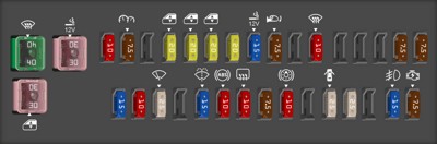
Instrument Panel Fuse Box Diagram
The second fuse box is located under the driver’s side instrument panel, inside the car. This fuse box generally manages interior and accessory systems, including power windows, interior lighting, the cigarette lighter, and importantly, the On-Board Diagnostic system (OBD2).
Below is a detailed list of the fuses in the instrument panel fuse box:
| Type | No. | Description |
|---|---|---|
| Fuse FMX/JCase 40A | 1 | (DEF) Rear window defogger, MIR HTR |
| Fuse FMX/JCase 30A | 2 | (PWR SEAT) Power seat |
| Fuse MINI 10A | 3 | (TAIL) Parking lights, tail lights, license plate lights, fron side marker lights, multiport fue injection system/ sequential multiport fuel injection system, instrument cluster lights |
| Fuse MINI 7.5A | 4 | (PANEL) Switch illumination |
| Fuse MINI 20A | 5 | (FR DOOR) Power windows. moon roof |
| Fuse MINI 20A | 6 | (RL DOOR) Power windows |
| Fuse MINI 20A | 7 | (RR DOOR) Power windows |
| Fuse MINI 20A | 8 | (SUNROOF) Moon roof |
| Fuse MINI 15A | 9 | (CIG) Cigarette lighter |
| Fuse MINI 7.5A | 10 | (ACC) Outside rear view mirrors, audio system main body ECU |
| Fuse MINI 10A | 11 | (MIR HTR) Outside rear view mirror defogger |
| Fuse MINI 7.5A | 12 | (IGN) Steering lock system, SRS airbag system, multiport fue injection system/sequentia multiport fuel injection system, front passenger occupant classification system |
| Fuse MINI 7.5A | 13 | (METER) Gauge and meters |
| Fuse FMX/JCase 30A | 14 | (POWER) Power windows |
| Fuse MINI 15A | 15 | (SEAT HTR) Seat heater |
| Fuse MINI 10A | 16 | (HTR-IG) Air conditioning system |
| Fuse MINI 25A | 17 | (WIPER) Windshield wipers |
| Fuse MINI 15A | 18 | (WASHER) Windshield washer |
| Fuse MINI 10A | 19 | (ECU-IG NO. 1) Automatic transmission, main body ECU, electric power steering, electric cooling fan(s), shift lock control system, anti-lock brake system, tire pressure warning system, vehicle stability control system, cruise control system |
| Fuse MINI 10A | 20 | (ECU-IG NO. 2) Back-up lights, charging system, rear window defogger, air conditioning system, multiport fue injection system/sequential multiport fuel injection system, moon roof |
| Fuse MINI 7.5A | 21 | (OBD) On-board diagnosis system |
| Fuse MINI 10A | 22 | (STOP) Stop lights, high mounted stoplight, anti-lock brake system, main body ECU, multiport fuel injection system/sequential multiport fuel injection system, shift lock control system, vehicle stability control system |
| Fuse MINI 25A | 23 | (DOOR) Power door lock system |
| Fuse MINI 25A | 24 | (ACC-B) CIG ACC |
| Fuse MINI 15A | 25 | (FR FOG) Front fog lights |
| Fuse MINI 7.5A | 26 | (AM1) Starting system, ACC. CIG |
2013 Toyota Corolla OBD2 Fuse Location and System
For those specifically looking for the 2013 Toyota Corolla Obd2 Fuse Location, you’ll find it in the instrument panel fuse box. Referring to the table above, fuse number 21, a 7.5A MINI fuse labeled (OBD), is dedicated to the On-Board Diagnostic system.
The OBD2 port is typically located under the driver’s side dashboard, near the steering column. This port is essential for connecting diagnostic scan tools to read vehicle data, check engine codes, and perform system diagnostics. If you are experiencing issues with your OBD2 scanner not powering up or connecting properly, checking the OBD fuse (7.5A) in the instrument panel fuse box should be one of your first troubleshooting steps.
Utilizing Fuse Diagrams for Troubleshooting
Understanding these fuse diagrams is invaluable for troubleshooting electrical problems in your 2013 Toyota Corolla. If a specific electrical component is not working, like your radio, headlights, or power windows, a blown fuse is often the culprit.
Here’s how to use these diagrams effectively:
- Identify the non-functioning component: Determine which electrical part of your car is not working.
- Consult the fuse diagrams: Locate the fuse box diagrams for your 2013 Toyota Corolla (engine compartment and instrument panel).
- Locate the relevant fuse: Using the tables, find the fuse associated with the non-functioning component. For instance, if your cigarette lighter isn’t working, look for “CIG” in the instrument panel fuse box table.
- Inspect the fuse: Once you’ve located the fuse, visually inspect it. A blown fuse usually has a broken wire inside or appears blackened.
- Replace if necessary: If the fuse is blown, replace it with a new fuse of the same type and amperage.
- Test the component: After replacing the fuse, test the electrical component to see if it now functions correctly.
Important Notes:
- Always replace a blown fuse with one of the same amperage rating. Using a fuse with a higher amperage can overload the circuit and cause further damage or even a fire.
- If a fuse blows repeatedly, it indicates a more serious underlying electrical problem that needs professional diagnosis and repair. Do not simply keep replacing fuses without investigating the root cause.
- Safety First: Always turn off the ignition and remove the key before working on your vehicle’s fuses.
By using this guide, you are now better equipped to understand the fuse box locations and the OBD2 fuse location in your 2013 Toyota Corolla. This knowledge empowers you to perform basic electrical troubleshooting and maintenance, keeping your vehicle running smoothly and safely.