Understanding your vehicle’s health is becoming increasingly important in today’s automotive world. The On-Board Diagnostics II (OBD2) system is a cornerstone of modern vehicle diagnostics, providing access to a wealth of data about your car’s performance and condition. If you’re looking to delve into the specifics of vehicle communication, particularly the 2008 Obd2 Ecu Pid Protocol, you’ve come to the right place. This guide will provide a comprehensive overview, going beyond a simple introduction to give you a deeper understanding of this critical system.
What is OBD2 and Why 2008 is a Key Year?
OBD2 is essentially your car’s self-diagnostic system. Think of it as a built-in doctor constantly monitoring various aspects of your vehicle’s operation. This standardized protocol allows mechanics and enthusiasts alike to retrieve Diagnostic Trouble Codes (DTCs) and real-time data through the OBD2 connector, typically located near the steering wheel.
You’ve likely encountered OBD2 in action already. That “check engine light” or malfunction indicator lamp (MIL) on your dashboard? That’s OBD2 signaling an issue. When you take your car to a mechanic, they use an OBD2 scanner to connect to this system, sending ‘OBD2 requests’ and receiving ‘OBD2 responses’. These responses contain valuable information like speed, engine temperature, fuel levels, and those crucial DTCs, enabling faster and more accurate troubleshooting.
Why is 2008 significant when we talk about OBD2? While OBD2 was mandated in the US for cars and light trucks in 1996, and later in Europe, 2008 marks a pivotal point in its evolution. In 2008, it became mandatory for all cars sold in the US to use the ISO 15765-4 standard, which specifies CAN (Controller Area Network) bus as the communication backbone for OBD2. This standardization was crucial for ensuring interoperability and streamlining diagnostics across different vehicle manufacturers. This shift to CAN bus as the primary protocol significantly impacted how Electronic Control Units (ECUs) communicated diagnostic data using Parameter IDs (PIDs).
Prior to 2008, various protocols were in use, leading to fragmentation and complexity. The 2008 mandate simplified the landscape, making CAN bus and the associated ISO 15765-4 standard the dominant force in OBD2 communication, especially concerning ECU data and PID requests.
Delving into OBD2 ECU Communication
At the heart of OBD2 lies the communication between an external diagnostic tool and your car’s ECUs. ECUs are essentially mini-computers controlling various vehicle systems like the engine, transmission, brakes, and more. OBD2 provides a standardized way to “talk” to these ECUs and retrieve diagnostic information.
This communication follows a request-response model. An OBD2 scanner sends a request message through the OBD2 connector. This request is typically directed to one or more ECUs. The ECU(s) then process the request and respond with data. This data exchange happens over the CAN bus network within the vehicle, if it’s a 2008 or newer US vehicle, or vehicles compliant with ISO 15765-4.
The OBD2 connector, standardized by SAE J1962, is a 16-pin interface that provides the physical connection point for diagnostic tools. Pins are assigned for power, ground, and the communication network (like CAN bus).
For vehicles adhering to the 2008 mandate, pins 6 (CAN High) and 14 (CAN Low) of this connector are specifically designated for CAN bus communication, ensuring standardized physical layer connectivity for OBD2 diagnostics.
Understanding OBD2 Parameter IDs (PIDs)
Parameter IDs, or PIDs, are fundamental to retrieving real-time data from your vehicle’s ECUs via OBD2. PIDs are codes used to request specific data parameters from the ECU. Think of them as addresses for different sensors and calculated values within your car’s systems.
When an OBD2 scanner sends a request, it includes a PID to specify what data it wants. The ECU, upon receiving this request, retrieves the corresponding value and sends it back in the response. Standardized PIDs are defined in SAE J1979 and ISO 15031-5, covering a wide range of parameters related to engine performance, emissions, and vehicle systems.
For example, PID 0x0D is universally recognized as “Vehicle Speed”. If an OBD2 tool sends a request with Mode 0x01 (Show current data) and PID 0x0D, the ECU will respond with the current vehicle speed.
OBD2 Modes and PIDs in 2008+ Vehicles:
OBD2 defines 10 standard “services” or “modes” (0x01 to 0x0A), each serving different diagnostic purposes. Mode 0x01, “Show current data,” is particularly relevant for PIDs as it allows you to request a wide variety of real-time parameters. For 2008 and newer vehicles using CAN bus as per ISO 15765-4, Mode 0x01 and its associated PIDs are crucial for accessing engine and emissions-related data.
While the standards define around 200 PIDs within Mode 0x01, not all vehicles support every PID. However, Mode 0x01 PID 0x00 (“Supported PIDs [01-20]”) is mandatory for any emissions-related ECU that supports OBD2 services. Requesting PID 0x00 is a common initial step to determine which PIDs a specific ECU supports. The response to PID 0x00 is a bitmask indicating the availability of PIDs in the range 0x01 to 0x20. Similar PIDs like 0x20, 0x40, and so on, are used to check support for subsequent PID ranges.
Example of OBD2 PID Request and Response (Vehicle Speed – PID 0x0D):
- Request: OBD2 Scanner sends a CAN message with:
- CAN ID: 0x7DF (Functional request to all OBD2 ECUs)
- Data:
02 01 0D(2 bytes of payload, Mode 0x01, PID 0x0D)
- Response: ECU (typically Engine Control Module – ECM) responds with a CAN message:
- CAN ID: 0x7E8 (Response from ECM)
- Data:
03 41 0D 32(3 bytes of payload, Response Mode 0x41 (0x01 + 0x40), PID 0x0D, Speed value 0x32)
In this example, the speed value 0x32 in hexadecimal translates to 50 in decimal. According to the PID specification for 0x0D, this value represents speed in km/h. Therefore, the vehicle speed is 50 km/h.
The OBD2 Protocol Stack: ISO 15765-4 and Beyond
The 2008 OBD2 ECU PID protocol heavily relies on the ISO 15765 standard suite, particularly ISO 15765-4, which defines “Diagnostics on Controller Area Network (CAN)”. Understanding this protocol stack is key to grasping the technical underpinnings of OBD2 communication in modern vehicles.
1. CAN Bus (ISO 11898): The Physical and Data Link Layer
CAN bus, standardized by ISO 11898, serves as the foundation for OBD2 communication in most cars since 2008. It’s a robust and reliable communication network designed for automotive applications. ISO 15765-4 mandates specific CAN bus parameters for OBD2:
- Bit Rate: 250 kbps or 500 kbps. 500 kbps is more common in passenger cars, while 250 kbps is often used in heavier vehicles.
- CAN IDs: Both 11-bit (standard) and 29-bit (extended) CAN identifiers are allowed. OBD2 typically uses 11-bit IDs for request/response.
- Data Length: Diagnostic CAN frames are limited to a maximum of 8 bytes of data payload.
2. ISO-TP (ISO 15765-2): The Transport Layer
OBD2 data, especially for requests like VIN retrieval or DTC responses, often exceeds the 8-byte payload limit of a single CAN frame. To handle this, OBD2 utilizes ISO 15765-2, also known as ISO-TP (Transport Protocol). ISO-TP enables the segmentation and reassembly of messages larger than 8 bytes over CAN. It provides mechanisms for:
- Segmentation: Breaking down large messages into smaller CAN frames.
- Flow Control: Managing the transmission of segmented messages to prevent data overflow.
- Reassembly: Reconstructing the original large message from the segmented CAN frames.
ISO-TP defines different frame types for multi-frame communication, including First Frame (FF), Consecutive Frame (CF), Flow Control (FC), and Single Frame (SF). For most PID data requests, single-frame communication suffices, but for larger data transfers, ISO-TP’s multi-frame capabilities are essential.
3. Diagnostic Services (SAE J1979 / ISO 15031-5): The Application Layer
SAE J1979 and its international equivalent ISO 15031-5 define the “application layer” of OBD2. This layer specifies:
- OBD2 Modes (Services): The 10 diagnostic services (0x01 – 0x0A) and their functionalities.
- Parameter IDs (PIDs): The standardized codes for requesting specific data parameters within each mode, particularly in Mode 0x01.
- Data Encoding and Scaling: Rules for interpreting the raw data bytes received in OBD2 responses and converting them into physical values (e.g., km/h, degrees Celsius).
- Diagnostic Trouble Codes (DTCs): Structure and format of DTCs for reporting diagnostic faults.
This layer sits atop ISO-TP and CAN bus, providing the high-level diagnostic commands and data definitions that make OBD2 a standardized and universally understood diagnostic system.
Practical OBD2 Data Logging and Decoding in the 2008+ Era
Logging and decoding OBD2 data from 2008 and newer vehicles, leveraging the standardized CAN bus and ISO 15765-4 protocol, has become more streamlined. Here’s a practical overview:
1. Setting up an OBD2 Data Logger:
To log OBD2 data, you’ll need an OBD2 data logger. These devices connect to your vehicle’s OBD2 port and record CAN bus traffic, including OBD2 request and response messages. For 2008+ vehicles, ensure your logger supports CAN bus and ideally ISO 15765-4.
Steps for Basic OBD2 Logging:
- Connect the Logger: Plug your OBD2 logger into the vehicle’s OBD2 port.
- Configure Logging Parameters: Depending on your logger, you might configure settings like bit rate (500 kbps is common for cars), CAN IDs to filter (optional, but can reduce data volume), and logging frequency.
- Start Logging: Initiate the logging process. The logger will capture CAN bus data as you drive or operate the vehicle.
- Retrieve Data: After logging, extract the recorded data from the logger (typically via SD card or USB).
2. Decoding OBD2 PIDs and Data:
Raw OBD2 data logged from the CAN bus is in hexadecimal format and needs to be decoded to be meaningful. Decoding involves:
- Identifying OBD2 Messages: Filtering the logged CAN data to isolate messages with CAN IDs related to OBD2 (e.g., request ID 0x7DF, response IDs 0x7E8-0x7EF).
- Parsing the Payload: Examining the data payload of OBD2 response messages. The first byte usually indicates the number of data bytes, followed by the response mode (e.g., 0x41 for Mode 0x01), the PID, and then the data bytes representing the parameter value.
- Applying PID Scaling and Units: Using OBD2 PID documentation (SAE J1979, ISO 15031-5, or online PID lookup tools) to determine the scaling factors, units, and formulas for converting the raw data bytes into physical values.
Using DBC Files for Decoding:
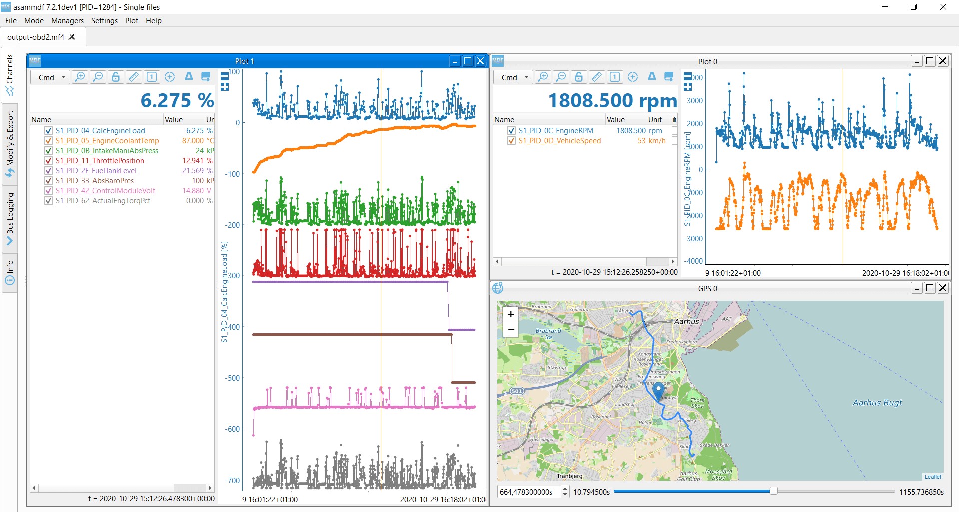
For easier decoding, especially when working with multiple PIDs, DBC (CAN database) files are invaluable. A DBC file for OBD2 contains definitions for common OBD2 PIDs, including their names, IDs, data types, scaling, and units. Software tools like asammdf can use DBC files to automatically decode raw CAN data, presenting you with human-readable parameter names and values.
OBD2 PID Lookup Tools:
Online OBD2 PID lookup tools can quickly provide information about specific PIDs, including their descriptions, modes, data byte interpretation, and formulas. These tools are helpful for understanding individual PIDs and verifying decoding results.
OBD2 Beyond 2008 and Future Trends
While 2008 marked a significant standardization milestone for OBD2 with the mandatory adoption of CAN bus and ISO 15765-4, the evolution of vehicle diagnostics continues. Trends like OBD3 and WWH-OBD (World-Wide Harmonized OBD) are emerging, aiming to further enhance and standardize vehicle diagnostics.
OBD3 envisions adding telematics capabilities to vehicles, potentially enabling remote emission monitoring and diagnostics. WWH-OBD seeks to harmonize OBD standards globally, leveraging the UDS (Unified Diagnostic Services) protocol for more advanced diagnostic functionalities.
However, the 2008 OBD2 ECU PID protocol, built upon CAN bus and ISO 15765-4, remains the dominant standard for accessing real-time data and diagnostic information from a vast majority of vehicles on the road today. Understanding this protocol is essential for anyone involved in automotive diagnostics, data analysis, and vehicle performance monitoring.
Conclusion: Mastering the 2008 OBD2 ECU PID Protocol
The 2008 OBD2 ECU PID protocol represents a crucial point in the standardization and accessibility of vehicle diagnostic data. The mandate of ISO 15765-4 and CAN bus for OBD2 in US vehicles from 2008 onwards simplified and streamlined vehicle communication, making it easier to access ECU data via standardized PIDs.
By understanding the principles of OBD2, the role of ECUs, the function of PIDs, and the underlying protocol stack, you can effectively leverage OBD2 for a wide range of applications, from basic vehicle diagnostics to advanced data logging and analysis. As the automotive landscape evolves, a solid grasp of the 2008 OBD2 ECU PID protocol will continue to be a valuable asset for anyone working with or interested in vehicle technology.
Explore techcarusa.com for more in-depth articles, tutorials, and resources on OBD2, CAN bus, and vehicle diagnostics.
Ready to explore OBD2 data logging?
Check out our recommended OBD2 data loggers
Contact us for expert advice on your OBD2 project