Experiencing electrical issues with your 2006 PT Cruiser can be frustrating. Before you jump to conclusions about complex problems, it’s wise to start with the basics and methodically check key components. This guide focuses on diagnosing a potential power issue by examining the Connector C104 and the ignition switch, crucial parts of your PT Cruiser’s electrical system. Understanding these checks is essential, whether you’re a seasoned DIY mechanic or just starting out with car maintenance, and it’s a foundational step even before considering OBD2 diagnostics for engine-related problems.
Before diving in, it’s worth revisiting the Totally Integrated Power Module (TIPM), a common area for electrical problems in PT Cruisers. Ensuring all connections to the TIPM are secure and wires are in good condition is a smart preliminary step. Have you already checked the power at the underside of the TIPM? If so, and you’ve confirmed the positive cable is good and ground connections are solid, let’s move further into the system.
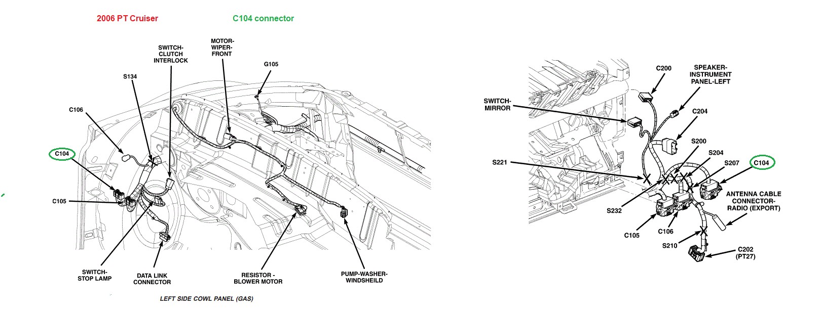
Our next step is to check for 12-volt power at connector C104, located under the dash on the driver’s side. Power for several systems, including the ignition, travels from fuse #4 at the TIPM, through this connector, and on to the ignition switch.
To access connector C104, you might need to remove a trim panel under the dash and steering column. Refer to your PT Cruiser repair manual if you’re unsure about trim panel removal.
Once you’ve located C104, carefully separate the connectors. On the side of the connector with the PK/DB (Pink/Dark Blue) wire, locate pin or cavity #42. For safety and to avoid damaging the small pins, use a back probe technique. Insert a paper clip into cavity #42 from the back of the connector to act as a probe point.
Using a test light, touch the probe (paper clip in #42) and ground the other lead of the test lamp to the steering column. Pin #42 should have constant power, meaning it’s not switched and should be live at all times. Does your test light illuminate?
- If NO: This indicates a problem with the PK/DB wire between connector C104 and fuse #4 in the TIPM. The issue could be anywhere along this wire’s path, including through the firewall and into the TIPM itself. Inspect the wire for breaks or damage.
- If YES: Power is reaching connector C104. Reconnect the male and female parts of connector C104. Now, back probe the RD (Red) wire at pin or cavity #42 on the C104 connector while it’s connected. Repeat the test light procedure, touching the probe and grounding to the steering column. The test light should illuminate again, indicating power is passing through the C104 connector itself. Does it light up this time?
If you have confirmed power at #42 on the RD wire after reconnecting C104, the next component to investigate is the ignition switch.
Accessing the ignition switch typically involves removing the steering column covers. This video for a 2004 PT Cruiser (procedure is similar for the 2006 model) may be helpful: [link to video – if available, otherwise remove this sentence]. You’ll likely need a tamper-proof TORX bit set to remove the ignition switch screws.
After freeing the ignition switch from its mounting, reconnect the electrical connector to it. The image below shows the pinout diagram for the 5-pin connector on the ignition switch.
Safety First: Before proceeding with ignition switch tests, ensure your PT Cruiser’s transmission is in PARK and the parking brake is firmly engaged. This prevents accidental starting during testing.
For these tests, back probe the connector at the ignition switch. Use your test light to check for power at cavity #5. There should be power here at all times.
Next, use a screwdriver to carefully turn the ignition switch to the ON/RUN position. Back probe cavity #3 and test for power. There should be power in this position.
Finally, turn and hold the ignition switch in the START position with the screwdriver. Test for power at both cavity #3 and cavity #4. Power should be present at both in the START position.
Report your findings for each of these tests. Knowing whether power is present at these points will help narrow down the source of your 2006 PT Cruiser’s electrical problem and guide you towards the next diagnostic steps. Remember, even though your PT Cruiser is OBD2 compatible for engine and emissions diagnostics, a solid electrical foundation is crucial for all vehicle systems to function correctly, and for accurate readings from any diagnostic tools you might use later.